SAILOR 100 GX system
2-6 Chapter 2: Introduction 98-141779-G
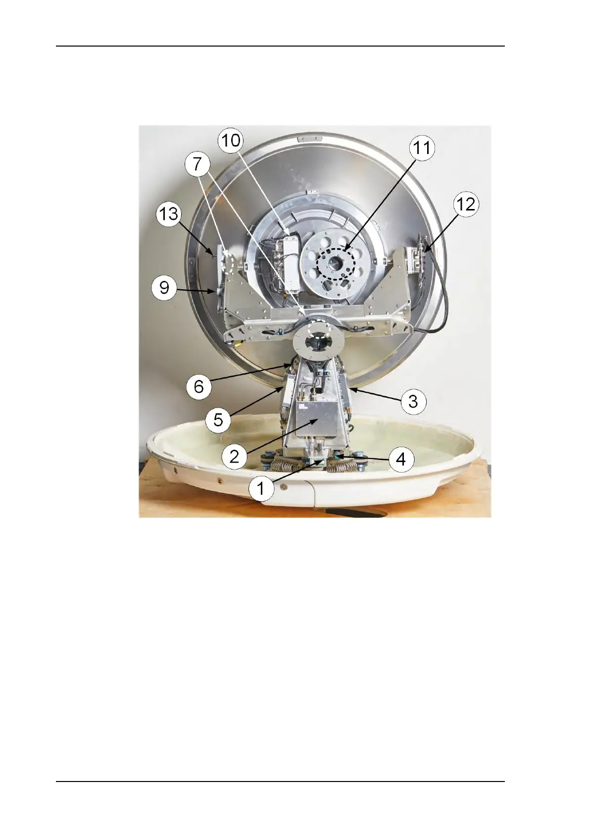
2.1.2.2 Modules in the SAILOR 100 GX-R2 ADU
1. GNSS module.
2. VSAT Interface Module (VIM).
3. Pedestal Control Module (PCM).
4. Service switch.
In switch-off position the Motor Driver modules is turned off for safe conditions during
service and repair. The switch must be set to on for normal operation.
5. Motor Driver Module for cross elevation (DDM/SMD).
6. Cross elevation motor and encoder.
7. Zero Reference Module (x3) (ZRM) (not visible on photo), (2 in the figure above, 1 in the
next figure).
8. Motor Driver Module for elevation (on the bottom) (DDM/SMD).
9. Elevation motor and encoder (not visible).
Figure 2-6: Above Deck Unit modules 1/2

 Loading...


