Installation of the ADU
98-141779-G Chapter 3: Installation 3-21
3333
If the ADU cannot or should not be electrically connected directly to the mounting surface,
you can use a separate grounding cable to make the connection between the ADU and the
common ground to which the ACU is also connected. If grounding to the ship ground is
impossible, for example if you have a fibre glass hull, see Alternative ground for fibre glass
hulls on page C-8. For further information on grounding and RF protection see the
appendix Ground and RF protection on page C-1.
3.3.6 Alternative ADU cable
The maximum allowed RF loss in the antenna cable is 20 dB RF loss @ 1950 MHz and
maximum 35 dB RF loss @ 4450 MHz.
You can verify the cable attenuation margin with the cable calibration, see Cable
calibration on page 6-12 for more details.
The DC-resistance loop of the antenna cable must be maximum 0.9 Ohm. This is to ensure
the power requirements from ACU to the antenna and to ensure the performance of the
system. Preferably choose one of the cable types listed in the table below.
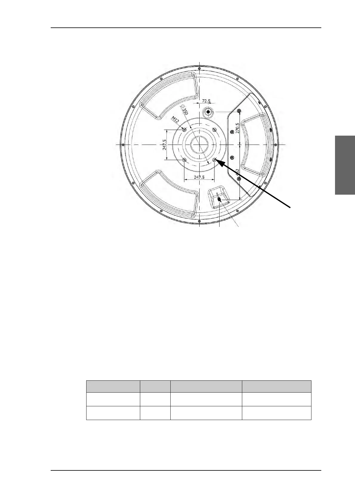
Figure 3-20: ADU, thread for optimum grounding
Cable type Thickness Absolute max. length (m) Absolute max. length (ft)
RG214 3/8” 50 m 160 ft
LMR-400-DB 0.405” 85 m 280 ft
Table 3-7: ADU cable types and maximum lengths

 Loading...


