Interfaces of the modem
4-8 Chapter 4: Interfaces 98-141779-G
4.2.4 LAN connectors (8 + 2)
The modem has 8 Ethernet connectors (type RJ45). Port 1 connects to the ACU and is used
for modem control. The other ports are not used. The maximum cable length per
connection is 100 m. The Ethernet cable type must be CAT5, shielded. For outline and pin
allocation see figure 4-7 on page 4-5.
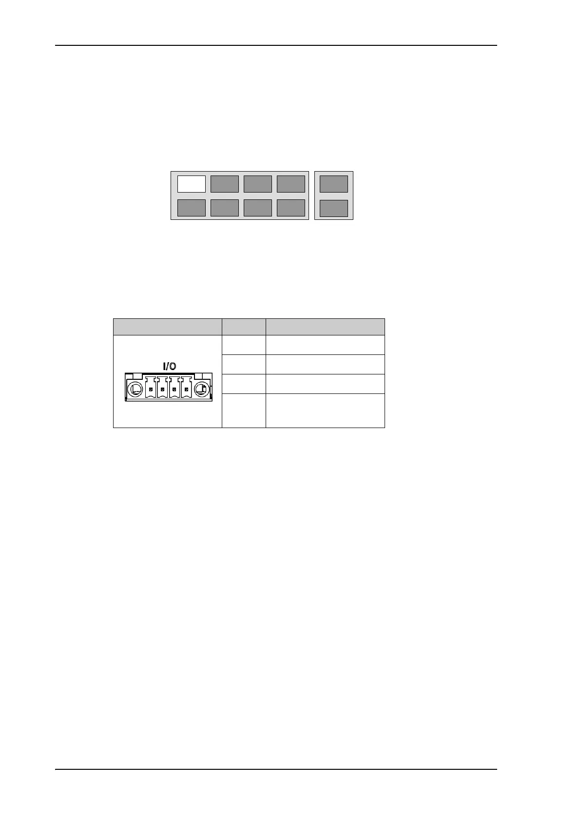
4.2.5 I/O connector for Tx Mute and Rx Lock (future use)
The GMU has one I/O connector for Tx Mute and Rx Lock.
Figure 4-4: LAN connectors at the modem, Port 1 (modem control) connects
to the ACU
Port 3 Port 4
Port 7 Port 8
Port 1 Port 2
Port 5 Port 6
Port 9
Port 10
Outline (on the GMU) Pin Pin function
1GND
2 Not connected
3Rx Lock out
4Tx Mute in
Table 4-11: I/O connector, outline and pin assignment, modem (future
use)

 Loading...


