Configuration with the web interface
6-24 Chapter 6: Configuration 98-141779-G
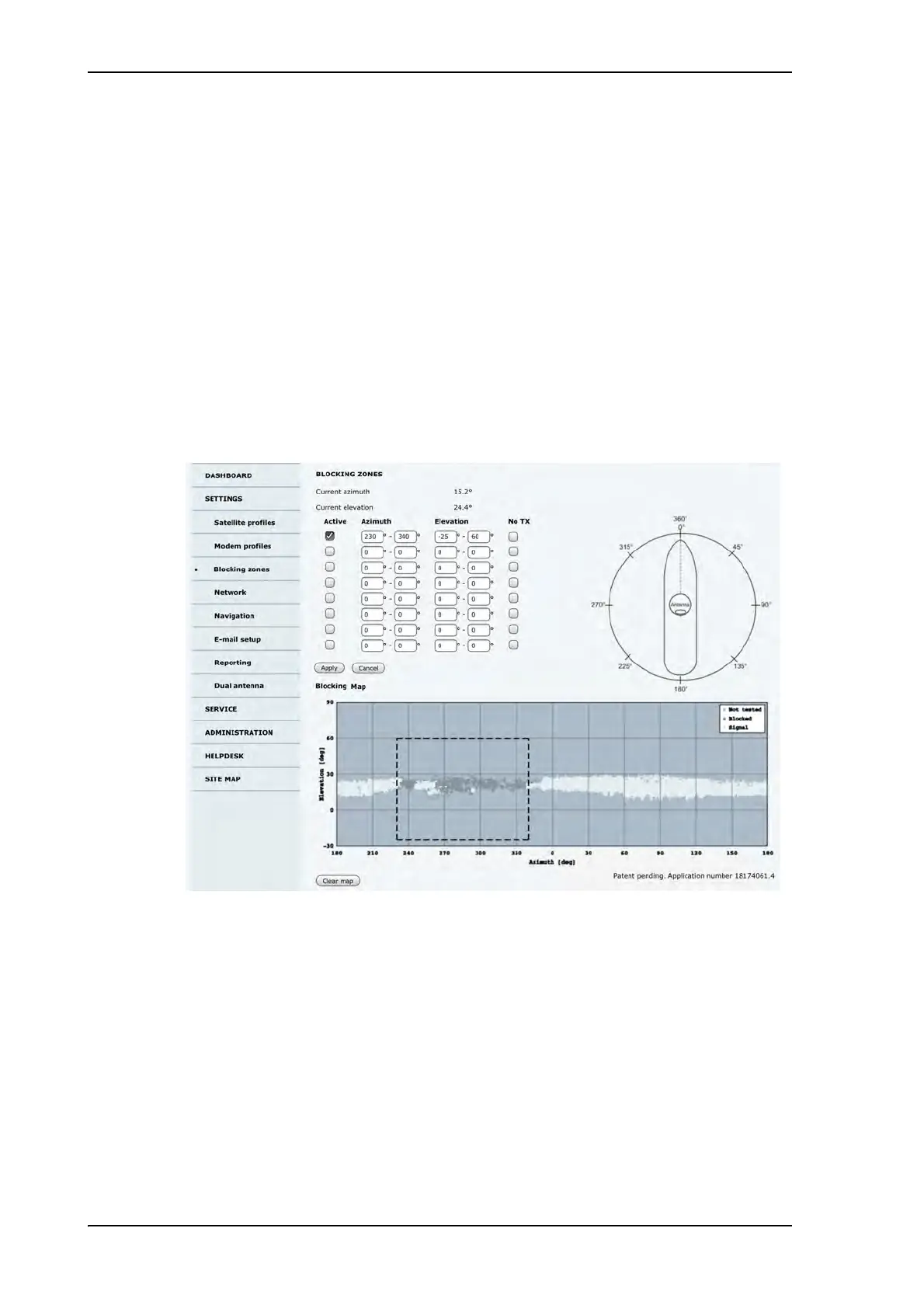
Optimization of the blocking zones
The blocking map is intended as a tool to optimise the blocking zones in order to reduce the
antenna’s downtime. It shows the active blocking zones and an automatic evaluation of the
antenna reception. Over time the antenna can determine where the signal is blocked by
structures on the ship. The blocking map helps you to set more accurate blocking zones.
To enable a blocking zone and display it on the blocking map you must select Active. The
re-defined zones will show immediately on the map.
The antenna updates the blocking map every 12 hours, showing whether the antenna has
been in a blocking zone (dark grey) or has received a signal (white). After a voyage of days,
weeks, months the blocking map will display where the blocking zones are on the vessel
(dark gray). The time it takes to draw a meaningful map depends on the ship’s size and
motions throughout the voyage. A small ship following a school of fish will have a
populated map faster than a larger tanker sailing across the Atlantic ocean.
The following figure shows a populated map.
6.4.3 To configure the LAN network
On this page you can enter a host name. The host name helps identifying the SAILOR 100
GX system when sending e-mail reports and remotely connecting through an external
Internet connection. The ACU has four 10/100 Mbit/s Ethernet ports labeled LAN port 1, 2,
Figure 6-18: Blocking zone and blocking map (example)

 Loading...


