Configuration with the web interface
98-141779-G Chapter 6: Configuration 6-23
6666
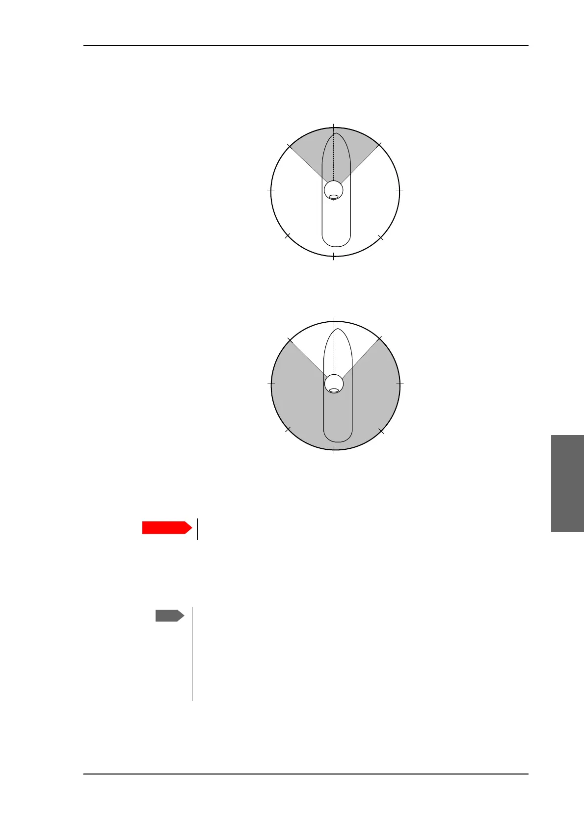
3. Enter start and stop azimuth values in degrees for the blocking zone. Values allowed: 0
to 360 degrees. Enter clockwise.
4. Enter the start and stop elevation angles for the blocking zone. If you enter nothing,
there will be no blocking zone. Values allowed: -30 to 90 degrees.
5. Select No TX for zones if you do not want the system to transmit when the antenna
points within this zone.
If No TX is not selected, the system also transmits when pointing through areas with
blocking objects. The modem will shut off for TX if no signal is received.
6. Click Apply to save the blocking zones.
Figure 6-16: Blocking zone, example: 315 - 45 degrees
Figure 6-17: Blocking zone, example: 45 - 315 degrees
You must enter 2 different elevation angles to have an active blocking zone.
If a blocking zone is defined with TX allowed (No TX not checked), the modem
is not informed about the blocking zone.
Modems may react differently when informed about a blocking zone, this has
influence on recapturing the link. The worst case is that the modem will search
the entire list of available satellites and frequencies when unaware of the
blocking zone, resulting in prolonged down times until the link is recaptured.
For optimum performance it is recommended to check No TX.
360°
000°
45°
90°
180°
135°225°
270°
315°
Antenna
Blocking zone:
315° - 45°
360°
000°
45°
90°
180°
135°225°
270°
315°
Antenna
Blocking zone:
45° - 315°

 Loading...


