SAILOR 100 GX system
2-8 Chapter 2: Introduction 98-141779-G
hatch on site. The ADU software is updated automatically when you make a software
update of the ACU.
2.1.3 Antenna Control Unit (ACU)
The ACU is the central control unit in the system. It contains all user interfaces and
manages all communication between the ADU and the connected modem, a connected PC
and an optional FleetBroadband service communication line. The ACU has a display, status
LEDs and a keypad. It provides a DHCP client. During configuration you can configure
heading offset, save satellite setup and enter No Transmit Zones (blocking zones in which
the ADU does not transmit). The user PC (user WAN) for Internet access etc. is connected
to the ACU, not the modem. The ACU provides DC power to the ADU through a single
coaxial cable. The ACU comes in a 19” rack version.
You can do remote diagnostics and service with the ACU. Its built-in test equipment
constantly checks the device for proper functioning. It performs POST (Power On Self Test)
and you can request a PAST (Person Activated Self Test). Continuous Monitoring (CM) is
also available. BITE error codes can be read out in the web interface and in the display of
the ACU. You can make a software update with a connected PC and the built-in web
interface of the ACU.
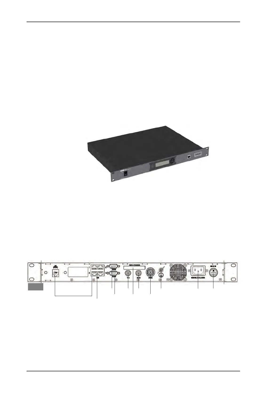
2.1.3.1 ACU interfaces
The ACU (SAILOR 7016C) has one LAN connector at the front and the following interfaces
at the rear panel:
• N-connector for ADU cable (50 Ohm).
• 2 x F connectors for Rx and Tx cables (75 Ohm) to modem.
• Multi connector for NMEA interfaces (for input from GPS compass or Gyro compass).
• RS-422 interface for modem control.
Figure 2-8: Antenna Control Unit
Figure 2-9: ACU (connector panel)
LAN 3 (Service) to front
Tx In
Rx Out
Ground
LAN 1-4
LAN 1 + 2: Modem control
RS-422 NMEA
AC Power
RS-232
Antenna
ACU
Fuse 7AT/SB
Type label

 Loading...


