InteliMains 210 Global Guide
573
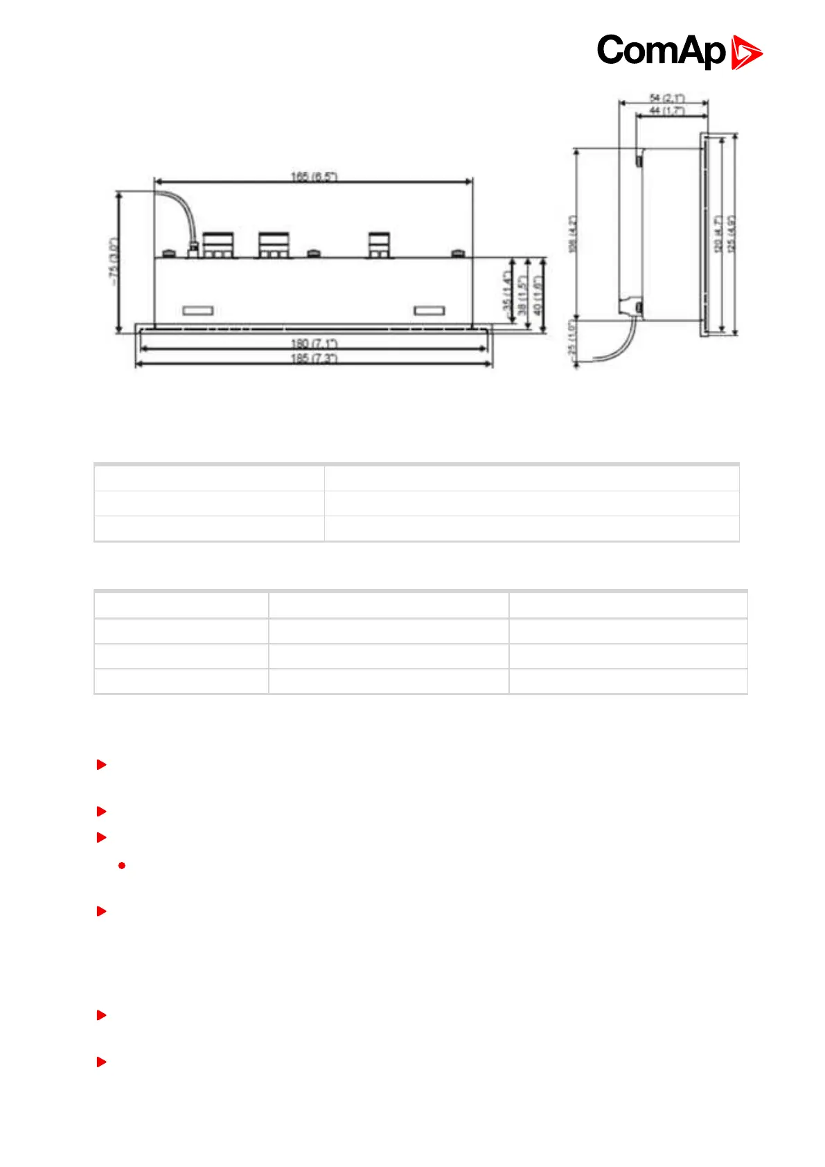
Image 8.178 IGL-RA15 dimensions
Terminals
Horn Horn
CAN CAN1 line
Power Power supply
CAN address
Address Jumper A Jumper B
1 OPEN OPEN
5+6 CLOSED OPEN
Customer defined CLOSED CLOSED
SW changing of CAN1 address is enabled only when both jumpers are closed. Any one of these addresses (1+2
or 3+4 or 5+6 or 7+8) can be set by following steps:
Switch to programming mode (Hold the Horn reset and Lamp test when unit is powering on). Status led is
yellow
Press Lamp test sixteen times
Set the address up by pressing Horn reset.
The number of red luminous LEDs means the CAN1 addresses (two for addresses 1+2, four for
addresses 3+4, six for addresses 5+6 and eight for addresses 7+8)
Press Lamp test
LED indication
Each LED color is adjusted independently of controller output settings. If controller output 1 is set as “Common
Shutdown” it doesn’t mean red LED1 color for iGL-RA15. The LEDs color can by adjust by following steps:
Switch to programming mode (Hold the Horn reset and Lamp test when unit is powering on). Status led is
yellow
Press Horn reset to change the LED1 color (green, yellow, red)
 Loading...