ComNav 1500 / 1510 Autopilot - 14 -
Installation
At the dock, hold the small pocket compass (supplied) in the proposed compass
location, and while keeping it pointed in one direction, slowly move it up and down
over about 3ft (1m). Then move it slowly fore-aft and athwartships over about 3ft
(1m) while keeping it on the same bearing and at the proposed mounting height. If
the compass heading does not change by more than 30°, the location is probably
acceptable. Another test is to temporarily mount a fluid compass at the proposed
Autopilot location and then turn the vessel slowly while comparing the compass
heading against the corrected main steering compass heading. If differences are
less than 30°, the automatic compass compensation will operate satisfactorily. The
automatic deviation may correct for much larger errors, but best Autopilot response
will be achieved if a location with low magnetic interference is chosen.
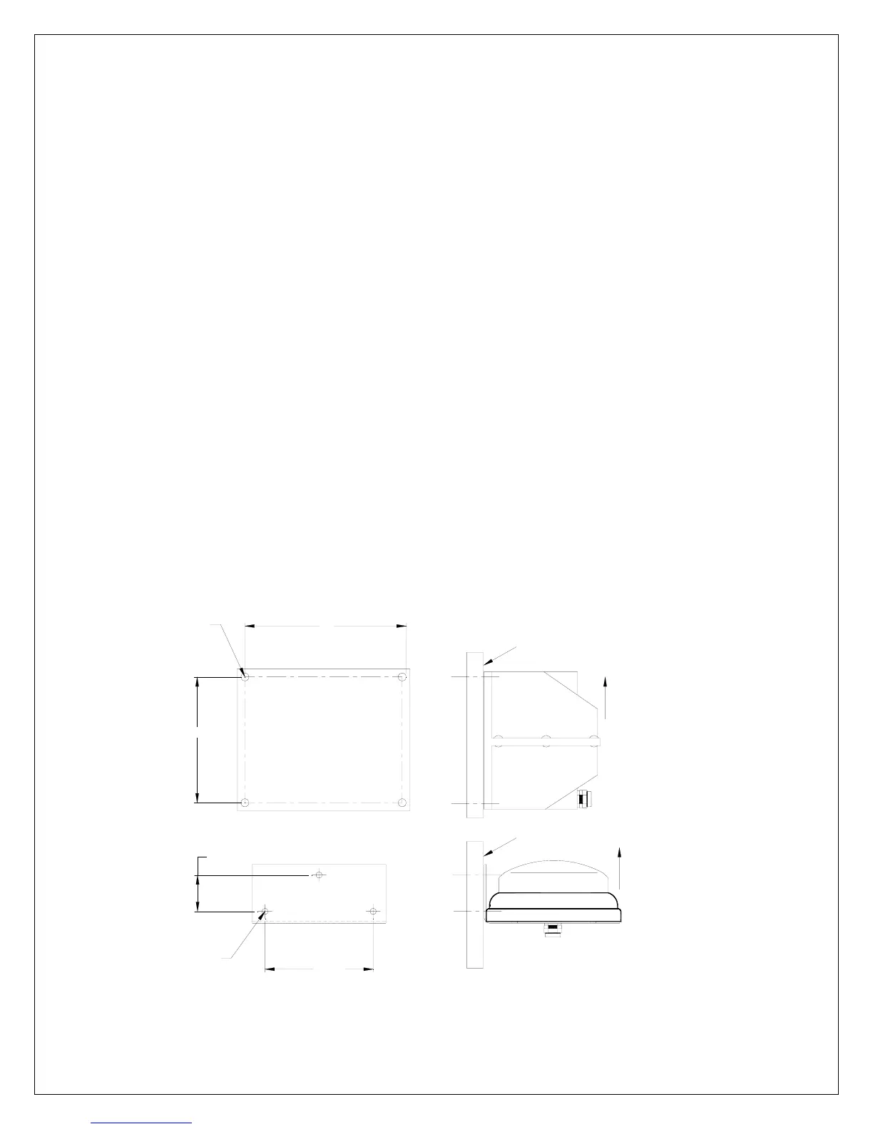
• 45° Compass: With cable outlet at bottom, place the compass on a flat vertical
surface and mark the 4 mounting holes. Drill accordingly and mount with
stainless steel fasteners.
• 35° Compass: With cable outlet at bottom, place the bracket on a flat vertical
surface and mark the 3 mounting holes. Drill accordingly and mount using
stainless steel fasteners.
Connect the compass cable to the Distribution Unit terminals #5, 6, 7and 8,
matching the colors as marked on the circuit board (see System Wiring Diagram).
VERTICAL BULKHEAD
UP
45° COMPASS TRANSDUCER
FLUID DAMPED FLUX GATE
VERTICAL BULKHEAD
COMPASS MOUNTING DIMENSIONS
5"
4"
Ø0.19"
(5mm)
4 HOLES
3.48"
1.56"
Ø0.19"
(5mm)
3 HOLES
35° COMPASS TRANSDUCER
FLUID DAMPED FLUX GATE
UP
For Both
1500 & 1510
Auto
ilots