ComNav 1500 / 1510 Autopilot - 16 -
If the locking screw in the Rudder Follower arm has been loosened, or the arm
removed from the Rudder Follower, re-attach the arm and check the potentiometer
center position. When the rudder is dead-ahead, the electrical resistance between
the black and green wires and the white and green wires should be equal (approx.
600 ohms each).
Be careful to check the installation for any mechanical obstructions or binding of the
linkage, and correct it now, before it becomes a problem.
The Rudder Follower is supplied with approximately 15.5m (50’) of cable. Run the
cable from the Rudder Follower towards the SPU, ensuring that a hose or conduit
protects it wherever it passes through fish or cargo holds, or any other area where
it could be damaged.
If the length of cable supplied is too short to reach all the way to the SPU, obtain a
terminal strip and sufficient additional cable from your dealer. Mount the terminal
strip in a convenient DRY location.
Connect cable to Distribution Unit terminals #8, 9, 10 and 11. Rudder Follower
Wires: shield to terminal #8 (Flux Gate shield), white to terminal #9 (marked red),
green to terminal #10 (marked white) and black to terminal #11 (marked black).
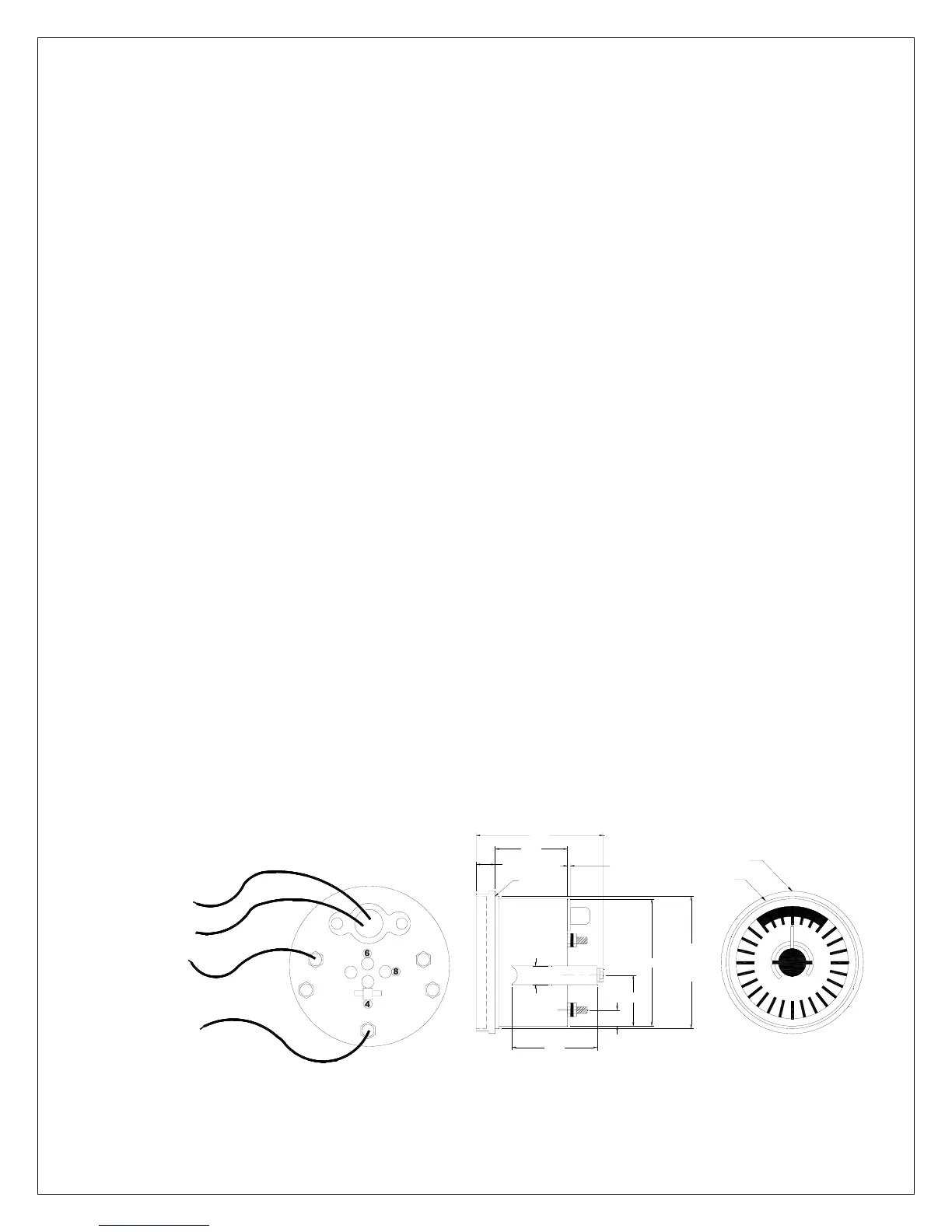
2.6 Analog Display Rudder Angle Indicator
Single or multiple analog display Rudder Angle Indicator repeaters can be added
as per the System Wiring Diagrams. If the rudder direction indication is reversed,
reverse the wiring connections at terminal #18 and #19 in the Distribution Unit. If a
ComNav Rudder Angle Indicator is fitted, adjustments of potentiometers VR2 and
VR3 on servo unit circuit board may be necessary. Potentiometer adjustment
details are outlined in Fine Tuning Section. If multiple Rudder Angle Indicators are
fitted, they must be wired in series.
10
20
30
40 40
30
20
10
BACKLIGHTING
TERMINAL #18
TERMINAL #19
SUPPLY
VOLTAGE
3.7"
0.6"
2.6"
0.6"
2.4"
CUT OUT
HOLE
Ø3.5"
Ø3.3"
1.2"
0.5"
O-RING
1/2"
CLEARANCE
Ø3.5"
Ø3.8"