Do you have a question about the Compaq W4000 and is the answer not in the manual?
Provides technical information about Compaq Evo D300/D500 and W4000 workstations.
Lists manufacturers' documentation and online resources for further information.
Explains the convention used for Compaq system model numbers and their components.
Describes the location and retrieval methods for the unit's serial number.
Details the notational guidelines used in the guide for values, ranges, and registers.
Lists acronyms and abbreviations used throughout the technical reference guide.
Provides an overview of Compaq Evo and Workstation systems, highlighting manageability and performance.
Describes the standard features and available options for all models.
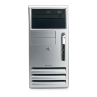
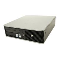
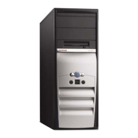
Details the mechanical aspects and form factors of the Compaq Evo models.
Explains the system architecture based on the Intel Pentium 4 processor and 845 chipset.
Lists environmental, electrical, and physical specifications for Compaq Evo and Workstation PCs.
Describes the processor/memory subsystem featuring Pentium 4 processor and 845 chipset.
Details the Intel Pentium 4 processor features, architecture, and overview.
Explains the system's support for SDR SDRAM and DDR SDRAM memory types.
Lists configuration registers for the processor/memory subsystem and PCI bus.
Introduces system support topics including bus architectures, resources, clock distribution, management, and registers.
Details the 32-bit Peripheral Component Interconnect (PCI) bus implementation, devices, functions, and transaction types.
Describes PCI bus transaction types including I/O, memory, and configuration cycles.
Explains the PCI bus master/target arbitration scheme and grant/request signal assignments.
Covers the process of scanning PCI bus for devices with firmware in ROM and loading into system memory.
Details the availability of interrupt signals (INTA-INTH-) for PCI devices and their routing.
Explains the system's compliance with PCI Power-Management Interface Specification.
Describes the Hub Link Bus and LPC Bus as supplementary to the PCI bus.
Details how PCI bus operations and parameters are configured via PCI configuration registers.
Provides pinout details for the 32-bit PCI bus connector.
Explains the Accelerated Graphics Port (AGP) bus, its design for graphics adapters, and differences from PCI.
Details AGP bus transactions, data transfer differences from PCI, and transaction types.
Describes how AGP bus operations and parameters are configured via PCI configuration registers.
Provides pinout information for the Universal AGP Bus Connector.
Explains the availability and basic control of subsystems known as system resources.
Describes the microprocessor's use of maskable and non-maskable interrupts and their handling.
Explains Direct Memory Access (DMA) and its role in allowing devices to access system memory.
Details the Intel CK-type clock generator and crystal used for generating system board clock signals.
Describes the RTC and CMOS functions provided by the ICH2 component and battery backup.
Covers system functions related to security, power management, temperature, and overall status.
Details security features like power-on passwords, cable lock provisions, and chassis sensors.
Explains the system's baseline hardware support for ACPI and APM firmware and software.
Provides visual indication of system boot and ROM flash status through keyboard LEDs.
Describes the system's thermal sensing logic and fan control mechanisms for cooling.
Contains the system I/O map and information on general-purpose functions of the ICH2 and I/O controller.
Describes standard system board interfaces for I/O porting and their control via registers.
Details the EIDE interface with primary/secondary controllers integrated into the chipset.
Explains how the IDE interface is configured as a PCI device and controlled through I/O-mapped registers.
Describes the 40-pin primary IDE connector for the hard drive and its signal redefinition.
Covers the diskette drive interface, its integration into the LPC47B357, and operational phases.
Explains diskette drive interface configuration and control during POST and runtime.
Provides pinout details for the standard 34-pin diskette drive connector.
Describes the two RS-232 type serial interfaces for asynchronous data transfer with external devices.
Details the DB-9 serial interface connector and its pinout.
Explains serial interface configuration and control using PnP registers and I/O-mapped registers.
Covers the parallel interface for peripheral connection, supporting SPP, EPP, and ECP modes.
Describes the Standard Parallel Port (SPP) mode with compatible and extended sub-modes.
Details the Enhanced Parallel Port (EPP) mode, featuring automatic address and strobe generation.
Explains the Extended Capabilities Port (ECP) mode with hardware protocol and FIFO support.
Covers parallel interface configuration and control during POST and runtime.
Provides pinout details for the DB-25 parallel interface connector.
Describes the keyboard/pointing device interface function provided by the LPC47B357 I/O controller.
Explains the data/clock link between the 8042 and keyboard, including Make and Break codes.
Details the pointing device interface, its connection, and signal control, using IRQ12.
Covers keyboard interface configuration and control, affecting 8042 logic and speed.
Describes the USB interface for asynchronous/isochronous data transfers up to 12 Mb/s.
Explains the NRZI encoding and bit stuffing used for USB data transmissions.
Covers USB interface configuration using PCI Configuration Registers and runtime control.
Describes the USB interface connectors, including front panel and rear panel types.
Provides recommended cable lengths and specifications for USB cables.
Details the two types of audio support: desktop/minitower and small form factor subsystems.
Describes the AC97 Audio Controller, its functions, and connection to the audio codec.
Explains the AC97 Link Bus used for communication between the audio controller and codec.
Details the AD1885 Audio Codec's function in PCM coding/decoding and analog channel mixing.
Covers audio subsystem programming, including configuration and control.
Lists the specifications for the integrated AC97 audio subsystem.
Describes the 10/100 Mbps NIC, its components, and features like auto-negotiation.
Explains Wake-On-LAN (WOL) support for booting the system from a powered-down state.
Details Alert-On-LAN (AOL) support for communicating events over a network when the system is off.
Covers NIC features for system wake-up, status messages, and APM/ACPI power management.
Explains NIC programming, including configuration via PCI registers and runtime control.
Shows the RJ-45 connector used for the NIC interface with status LEDs.
Lists the operating specifications for the 82559 NIC.
Discusses using the integrated NIC with another card or upgrading it.
Describes the power supply and method of general power and signal distribution.
Details the power supply assembly and its control through programmable logic.
Explains how the power supply assembly is controlled by the PS On signal and power button.
Covers power management functions designed to conserve energy using hardware, firmware, and software.
Describes the routing of DC voltages from the power supply to the system board and drives.
Explains how voltages less than 3.3 VDC, including processor core voltage, are produced.
Illustrates general signal distribution between main subassemblies like system board and graphics card.
Describes the BIOS ROM as machine language programs supporting POST, initialization, and setup.
Explains how system BIOS firmware in flash ROM can be rewritten for upgrading.
Covers BIOS functions related to the boot process, including device order and network booting.
Details the Serial Presence Detect (SPD) method for DIMM configuration and BIOS steps.
Lists visual and audible indications of failed system boot using keyboard LEDs and system speaker.
Allows users to configure system functions like security, power management, and resources via ROM-based utility.
Lists client management BIOS functions supported by systems for intelligent manageability applications.
Explains the INT 15, AX=E800h BIOS function to identify system type and ROM family.
Describes the BIOS function INT 15, AX=E813h for retrieving VESA extended display identification data.
Details the BIOS function (INT15, AX=E816h) to retrieve system interior temperature status.
Explains Compaq BIOS support for Drive Fault Prediction for IDE-type hard drives.
Lists the Plug 'n Play (PnP) functions supported by the BIOS.
Details how PnP functions retrieve SMBIOS data for structure information.
Covers power management support: independent PM, APM, and ACPI.
Explains how BIOS provides power management independently from the operating system.
Confirms system hardware and firmware meet ACPI compliance requirements.
Details APM as an extension of power management where the OS decides power state transitions.
Describes how BIOS checks the USB port for a keyboard during POST for ROM-based setup.
Lists error codes and provides brief descriptions of probable error causes.
Correlates beep patterns and keyboard LED status with specific error conditions.
Lists POST error messages and their probable causes for system diagnostics.
Provides a list of system error messages and their probable causes.
Lists memory error messages and their probable causes.
Lists keyboard error messages and their probable causes.
Lists printer error messages and their probable causes.
Lists video and graphics error messages and their probable causes.
Lists diskette drive error messages and their probable causes.
Lists serial interface error messages and their probable causes.
Lists modem communications error messages and their probable causes.
Lists system status error messages and their probable causes.
Lists hard drive error messages and their probable causes.
Lists hard drive error messages (19xx-xx) and their probable causes.
Lists video and graphics error messages (24xx-xx) and their probable causes.
Lists audio error messages (3206-xx) and their probable causes.
Lists DVD/CD-ROM drive error messages (33xx-xx) and their probable causes.
Lists network interface error messages (60xx-xx) and their probable causes.
Lists SCSI interface error messages and their probable causes.
Lists pointing device interface error messages and their probable causes.
Lists the 256-character ASCII code set with decimal and hexadecimal values.
Describes the standard Compaq keyboard, its features, and types.
Explains the functional block diagram of keystroke processing elements and scan code generation.
Details how PS/2 keyboards send data to the system, including timing and operating modes.
Explains how USB keyboards send data, including NRZI encoding and SMI generation.
Shows key layouts for standard, Windows-enhanced, and Easy Access keyboards.
Describes keyboard keys, including Make/Break codes, typematic action, and special functions.
Lists commands that the keyboard can send to the system's 8042 logic.
Explains how scan codes are generated based on the keyboard's operating mode.
Describes the PS/2 and USB keyboard interfaces, connectors, and pinouts.
Describes the Compaq/NVIDIA Vanta LT AGP Graphics Card for high 2D and 3D performance.
Details the NVIDIA Vanta LT Graphics Controller's features and capabilities.
Lists the 2D graphics display modes supported by the NVIDIA Vanta LT Graphics Card.
Covers software compatibility and driver support for legacy and extended video modes.
Explains monitor power control via DPMS protocol and card power consumption.
Describes the graphics card's connectors, including the monitor and feature connectors.
Describes the Compaq/NVIDIA Quadro2 EX and MXR AGP Graphics Cards for 2D/3D imaging.
Details the NVIDIA Quadro2 MXR Graphics Card's features for 2D and 3D display imaging.
Lists the 2D graphics display modes supported by the NVIDIA Quadro2 MXR Graphics.
Covers software compatibility for legacy video modes and driver support for extended modes.
Explains monitor power control using DPMS protocol and the card's power consumption.
Describes the graphics subsystem connectors: display/monitor and feature connectors.
Describes the Compaq/Matrox Millennium G450 AGP Graphics Card for 2D performance and 3D capabilities.
Details the Matrox Millennium G450-SD Graphics Card's features for 2D and 3D display imaging.
Lists the graphics display modes supported by the Matrox G200 MMS Graphics card.
Covers software compatibility for legacy video modes and driver support for extended modes.
Explains monitor power control using DPMS protocol and the card's power management.
Describes the graphics subsystem connectors: two display/monitor connectors and the feature connector.
Describes the Compaq/Adaptec 29160N SCSI Host Adapter as a PCI peripheral for SCSI devices.
Details the AIC-7892 SCSI controller architecture and its capabilities.
Covers SCSI adapter configuration and control using PCI protocol and I/O mapped registers.
Lists the operating specifications for the Ultra SCSI Host Adapter Card.
Describes the internal and external SCSI connectors on the card.
Describes the Compaq/Matrox G200 MMS Quad-Head PCI Graphics Card for multi-monitor imaging.
Details the Matrox G200 MMS Quad-Head PCI Graphics Card's multi-monitor 2D imaging capabilities.
Lists the graphics display modes supported by the Matrox G200 MMS Graphics card.
Explains single-card and multi-card display configurations supported by the graphics card.
Covers software compatibility for legacy video modes and driver support for extended modes.
Explains monitor power control using DPMS protocol and the card's power management.
Describes the graphics card's connectors: analog monitor, digital monitor, and adapter cable.