Technical Reference Guide
F.6 CONNECTORS
There are three connectors associated with the graphics subsystem; two display/monitor
connectors and the Feature connector.
NOTE: The graphic card’s edge connector mates with the AGP slot connector on the
system board. This interface is described in chapter 4 of this guide.
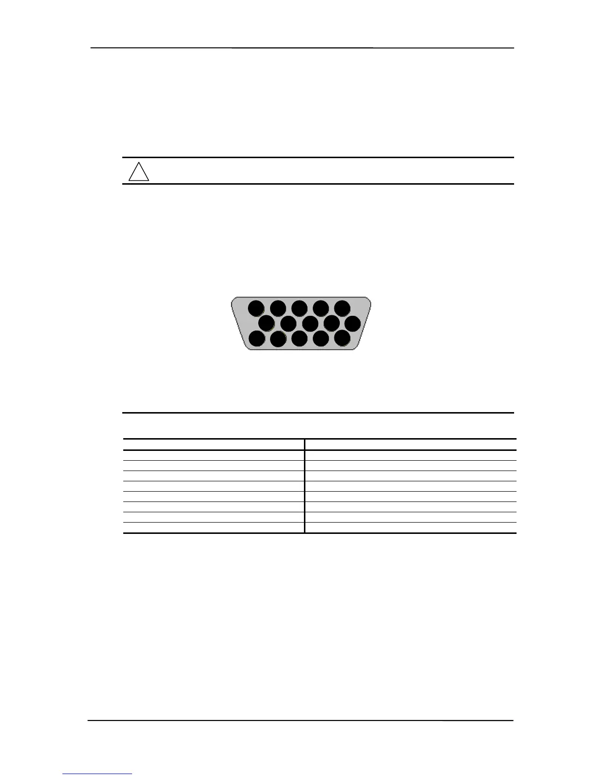
F.6.1 MONITOR CONNECTOR
The display/monitor connector is provided for connection of a compatible RGB/analog monitor.
1 2 3 4 5
6
7
8 9
10
11
12 13
14
15
Figure F-3. VGA Monitor Connector, (One of two female DB-15, as viewed from rear).
Table F-3. DB-15 Monitor Connector Pinout
Table F-3.
DB-15 Monitor Connector Pinout
Pin
Signal
Description Pin Signal Description
1 R Red Analog 9 PWR +5 VDC (fused) [1]
2 G Blue Analog 10 GND Ground
3 B Green Analog 11 NC Not Connected
4 NC Not Connected 12 SDA DDC2-B Data
5 GND Ground 13 HSync Horizontal Sync
6 R GND Red Analog Ground 14 VSync Vertical Sync
7 G GND Green Analog Ground 15 SCL DDC2-B Clock
8 B GND Blue Analog Ground -- -- --
NOTES:
[1] Fuse automatically resets when excessive load is removed.
Compaq Personal Computers
Original - November 2000
F-5