Technical Reference Guide
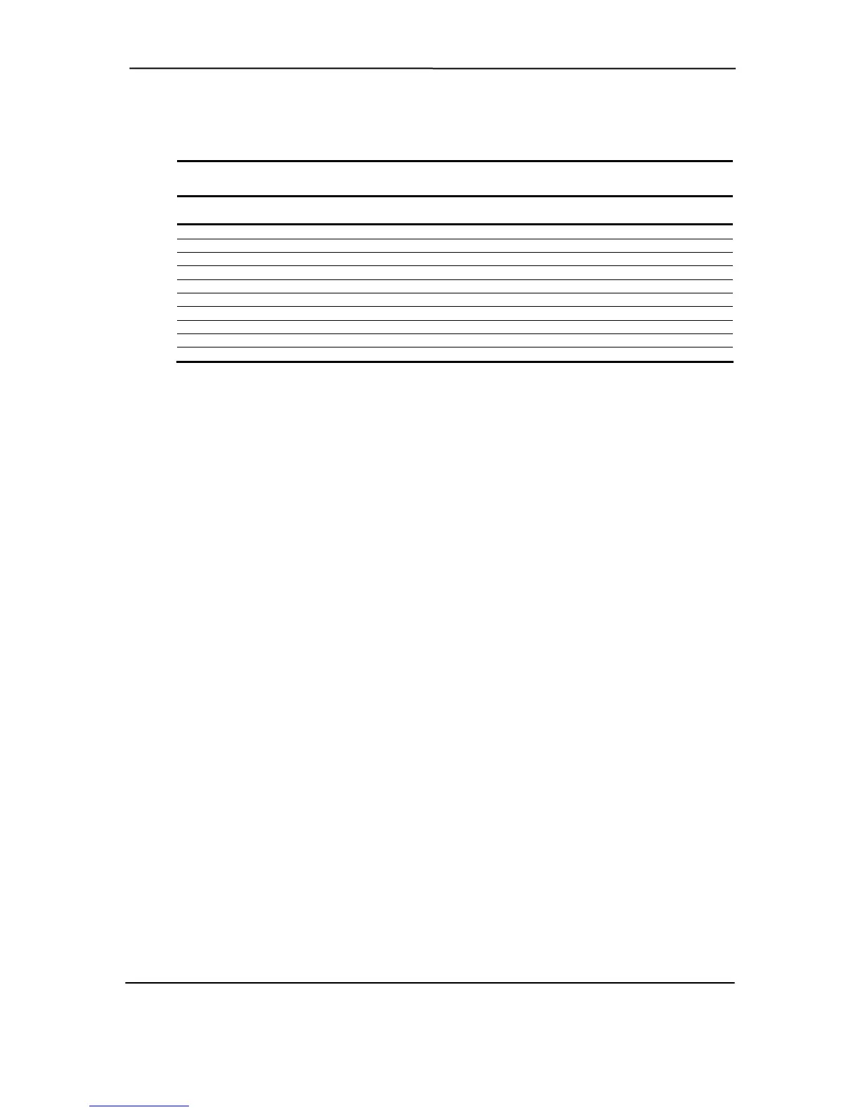
Table 4-16. System Operational Status LED Indications
l Status LED Indications
Table 4-16.
System Operationa
stem Status
Power
LED
Hard Drive
LED Sy
S0: System on (normal operation) Steady green Green w/HD activity
S1: Suspend Blinks green @ 1 Hz Off
S3: Suspend to RAM Blinks green @ 1 Hz Off
S4: Suspend to disk Blinks green @ 0.5 Hz Off
S5: Soft off Off - clear Off
Processor not seated Stead Off
CPU thermal shutdown Off (system p n) Off (system powers down)
er Blinks red @ 1 Hz Off
er supply rowbar activated .5 Off
stem off Off Off
RM EN AND COOLING
stems feature a v of the power supply ass ly. All systems also
de a system board connection for a processor fan, which is prese units. Desktop and
gurable Minitower systems provide an auxiliary chassis fan. All fans are controlled through
y red
owers dow
ROM ror
cPow Blinks red @ Hz
Sy
4.7.4 HE
ll sy
rovi
onfi
temperature sensing logic both on the system board and in the power supply. Electrically, there
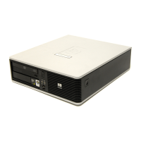
are slight differences between the Small Form Factor (Figure 4-11) and the desktop and
eration is the same.
An ASIC monitors a thermal diode internal to the processor and provides a Fan CMD signal that
e Speed Control logic uses to vary the speed of the fan(s) through the negative terminal of the
n(s). The turning off of the fan(s) as the result from the g placed
ondition is initiated by the control ASIC asserting the Fan Off- signal, which results in the
n/Off Control logic shutting off the +12 volts to the fan(s).
he main differences between the system types are as follow
In the Small Form system the processor fan, controlled by a separate speed control
ci t, is mounte nt of the chassis (separate from heat sink
conduct across heat sink by an air ba .
Desktop onfigurable Minitower systems use an integrated heat sink/fan assembly, with all
fans speed-controlled by the ASIC through the power supply so that a thermal condition of
the processor or power supply will affect all fans simultaneously.
ypical cooling conditions include t lowing:
1. Normal – Low fan speed.
n(s).
4. Sleep state – Fan(s) turned off. Hot processor or power supply will result in starting fan(s).
T AL S SING
A ariable-speed fan as part emb
nt in all p
C
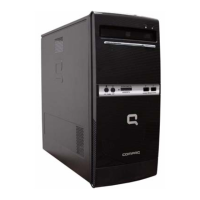
configurable minitower (Figure 4-12), although functionally op
th
fa system bein into a Sleep
c
O
T s:
Factor
d in the fro
♦
rcui
ed
/C
the
assembly) and air is
the processor's ffle
♦
T he fol
2. Hot processor – ASIC directs Speed Control logic to increase speed of fa
3. Hot power supply – Power supply increases speed of fan(s).
Compaq Evo and Workstation Personal Computers
Featuring the Intel Pentium 4 Processor
Second Edition - January 2003
4-29