51
4) To attach the fast door mounting plate (Figure # 34), there are four (4) fasteners provided.
The mounting plate attaches to the holes closest to the leading edge of the door panel.
Ensure the extended PEM nuts face inward towards the door panel.
5) Bolt the top link and door bracket (Figure # 33, Item # 3) of the sill closer to the mounting
plate on the fast door using the two (2) vertical holes closest to the leading edge.
6) Attach the slow door connecting link (Figure # 33, Item 4A) to the mounting bracket on the
rear of the slow door.
7) Bolt the base and yoke (Figure # 33, Item # 2) to the aluminum sill using the holes
previously drilled. Align the base and yoke parallel to the sill and tighten the bolts.
The door panels can now be operated as a "linked" pair. Open and close the door to ensure
proper and smooth operation. The only adjustment required for the sill closer is the spring
tension.
8) Adjust the spring (Figure # 33, Item # 6) until the door closes from the fully open position
to the fully closed position on its own.
NOTE
The spring tension should be set just enough to close the doors. Don't set it too strong.
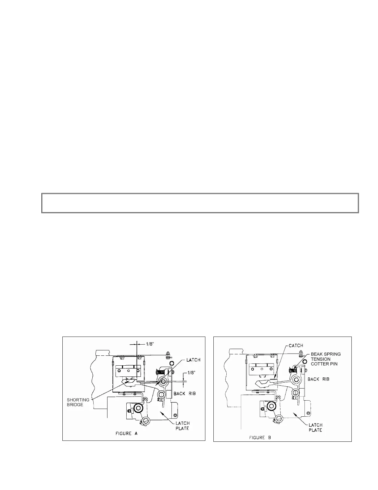
Installing/Adjusting the Lock
The Concord 6940V interlock is a "handed" device so it is important to have the proper hand
interlock for each landing.
1) Mount the latch plate (beak assembly) (Figure # 35 and # 36) to the fast door using the
four (4) holes provided in the fast door. Use the two (2) holes that position the beak
closest to the leading edge of the door. The other two holes are used when the door is the
reverse hand.
2) Position the 3/8" (10 mm) bolts in the center of the slotted holes. The latch plate should
be set level and parallel to the sill.
Figure # 35 Lock Contact Adjustment
Figure # 36 Lock Catch Adjustment