91
SERVICING THE CABLE HYDRAULIC ELEVATOR CYLINDERS
The cylinders have been designed with simplicity in mind and have a small number of moving
parts that may have potential for failure. These elevator cylinders will give the user thousands
of cycles under normal use if the elevator cylinder has been correctly installed, the hydraulic
system pressure has been correctly set, the hydraulic oil is of the correct type, and most of all,
is clean and free of contaminants.
In the event leakage around the cylinder is visible, the cylinder should be inspected by
qualified personnel only. Since this occurrence is rare, it is necessary to first determine the
cause/source of the leakage. Leakage will normally occur only if some physical damage has
happened or if environmental conditions have caused excessive corrosion to the working parts
of the cylinder.
PROCEDURE FOR RE-SEALING CYLINDERS
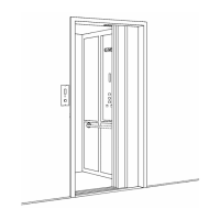
Refer to Figure # 58 for detailed drawing.
1) Be sure that the cylinder is not under any hydraulic pressure before attempting to service
it. The following simple test can be performed to determine if the pressure is at zero:
With the passenger platform fully secured or blocked at least twelve (12) inches above its
fully lowered position, remove the bolt that secures the cylinder piston rod to the yoke and
continue to lower the piston rod until it has fully bottomed within its outer casing. Then
proceed to “crack loose” the bleed nipple (Figure # 58, Item # 9) and visually look for oil
escaping from the nipple. If no oil is visible then remove the nipple completely. The
cylinder’s internal chamber is now open to the atmosphere and no pressure differential
will exist.
2) Proceed to remove the five (5) Socket Head Cap Screws (Item # 4) from the Gland Cap
(Item # 3).
3) Remove the Gland Cap by rotating and lifting the cap vertically until it comes free of the
cylinder casing and piston rod. It may be necessary to tap the Gland Cap lightly with a
soft mallet to initially free it from the cylinder casing.
4) Remove the O Ring (Item # 8) from the top of the cylinder casing and clean the recessed
groove area thoroughly where the O Ring is normally fitted. There must be no scratches,
nicks, or corrosion in this area.
5) From inside the Gland Cap remove the Rod Wiper (Item # 5), the U-Cup Rod Seal (Item
# 6), and the Wear Ring (Item # 7). To remove these items it may be necessary to use a
blunt screwdriver to pry them from their corresponding grooves. Be careful not to create
any scratches or nicks in this process. Once all of the items have been removed,
thoroughly clean and inspect the Gland Cap for any internal nicks, or scratches.
6) The fitting of the new seals should be made in the following order:
a) Install the new Wear Ring (Item # 7) into the corresponding groove in the Gland
Cap.