7
© Control Concepts Inc., 2013
www.ccipower.com 1-800-765-2799
Compact FUSION Installation Manual Revision 3.50.2
4
STEP
5
Make a 1/4 DIN (3.627” x 3.627” [92.13mm x 92.13mm])
size hole in the cabinet.
STEP
6
Place the gasket on the back of the display. Make sure
the gasket does not overhang the edges of the display.
Place the display inside of the 1/4 DIN cutout of the
cabinet with the display facing outward.
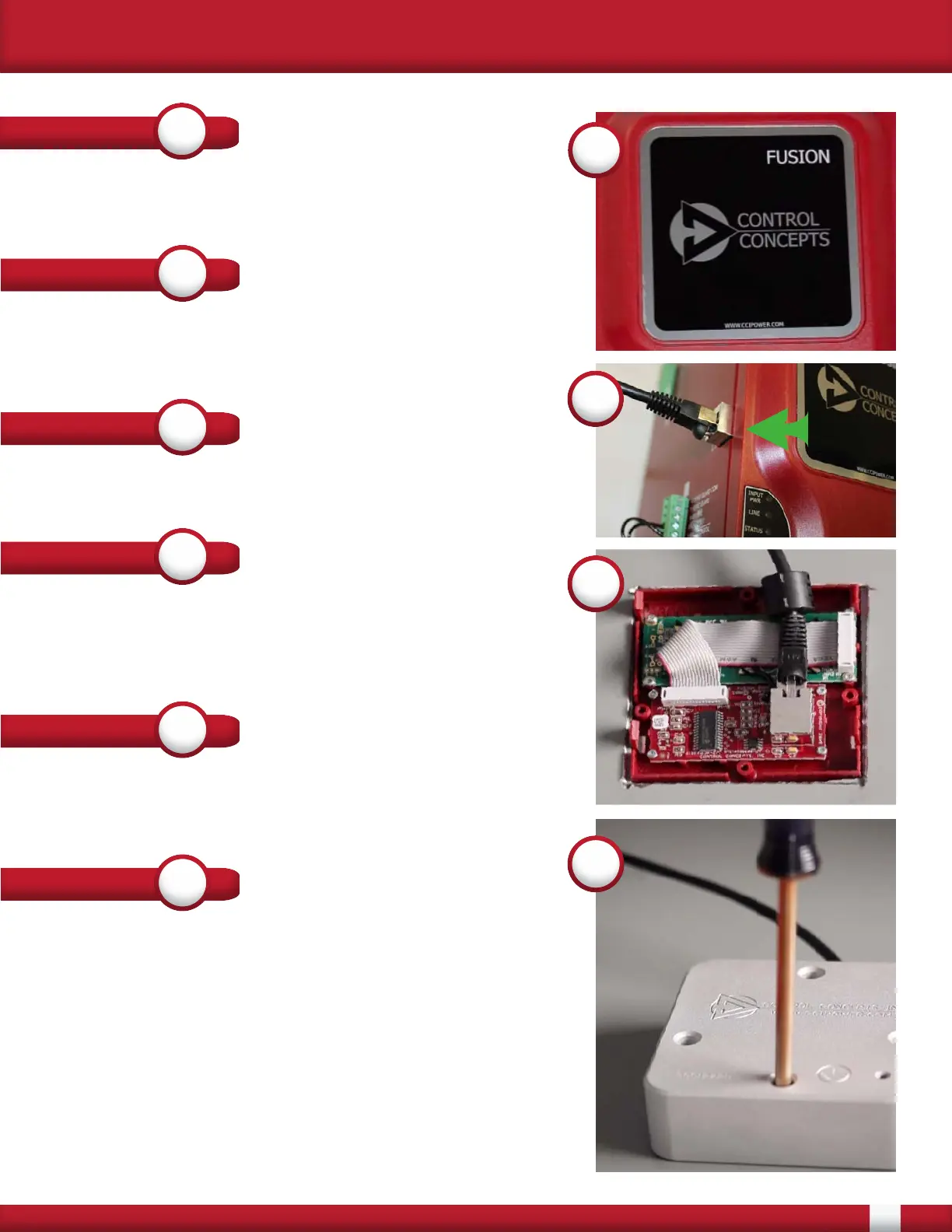
5
Remove the 1 foot cable from the display. Run one end
of the 5 or 25 foot cable to the Remote Display connector
on the side of the controller (See Number 5, right)
STEP
7
STEP
8
Attach the display retainer with provided mounting
screws. When tightening down the display make sure to
apply equal pressure to each screw to ensure the gasket
seals properly. When properly installed the gasket shall
be compressed 50% on all sides. If the gasket becomes
damaged during installation please contact Control
Concepts for a replacement.
When the controller is supplied with the Universal input
power [100-240 Vac] the display shall now operate the
same as when mounted on the controller
STEP
9
Attach the other end of the 5 or 25 foot shielded cable to
the connector on the display. Place the ferrite as close to
the connector as possible. (See Number 8, right)
8
9
STEP
4
Insert the empty display into the lid and reattach to the
controller. (See Number 4, right)