2
© Control Concepts Inc., 2013
www.ccipower.com 1-800-765-2799
Compact FUSION Installation Manual Revision 3.50.2
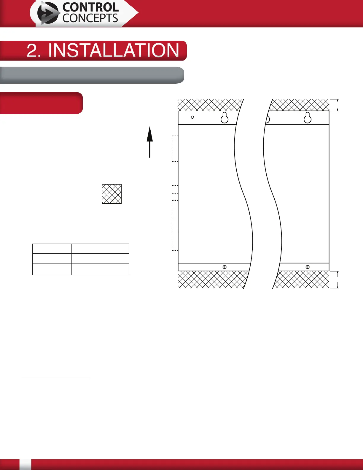
Keep out area for top and bottom:
Mount 10 and 25 Amp controllers and a 1 zone 50 Amp single phase controller vertically for
convection cooling. All other controllers have forced air cooling and may be mounted horizontally or
vertically.
The keep out area on the top and bottom must be maintained for air circulation. The top and bottom
of the controller must have a minimum of 3.00 [76.2] free from obstructions as measured from fan
guards. Dimensions above are measured from the edge of the base plate.
Mounting hardware: 1/4-20 or M6 bolts with flat and lock washers (not provided)
P1, P2 and P3 protrude approximately 0.50 [12.7] from the left side of this figure. When using the
remote display, this distance is approximately 2.25 [57.2]. They are required for operation but
may be removed for wiring. It is important to leave enough room for the removal of the connectors
(approximately 1.00 [25.4] - More if using Remote Display) and wiring considerations.
CAD Blocks are available for download at www.ccipower.com.
Keep Out Area
Air Flow
2. INSTALLATION2. INSTALLATION
2.1 Mounting Considerations
*Depth with DeviceNet adaptor is 9.82 [249.4]
A 1.82 [46.2]
B 2.31 [58.7]
Depth* 9.57 [243.0]
B
A
P1
P2
P3
Remote
Display
Dimensions:
Inches [mm]