22
© Control Concepts Inc., 2013
www.ccipower.com 1-800-765-2799
Compact FUSION Installation Manual Revision 3.50.2
P1
P2
P3
P4
12 SYNC GUARD COM
11 SYNC GUARD
10 SP1/SP2
9 RUN/RESET
8 ANALOG/DIGITAL
7 COM
6 COM
5 (-) IN 2
4 (+) IN 2
3 (-) IN 1
2 (+) IN 1
1 +5Vdc POT
SETPOINT
A
B
0/5 Vdc
+
-
4/20 mA
+
-
12 SYNC GUARD COM
11 SYNC GUARD
10 SP1/SP2
9 RUN/RESET
8 ANALOG/DIGITAL
7 COM
6 COM
5 (-) IN 2
4 (+) IN 2
3 (-) IN 1
2 (+) IN 1
1 +5Vdc POT
SETPOINT
POT 1 POT 2
W2
W1
CW
B
C
CCW
3.5 Connectors
P1 P2
P3
P4
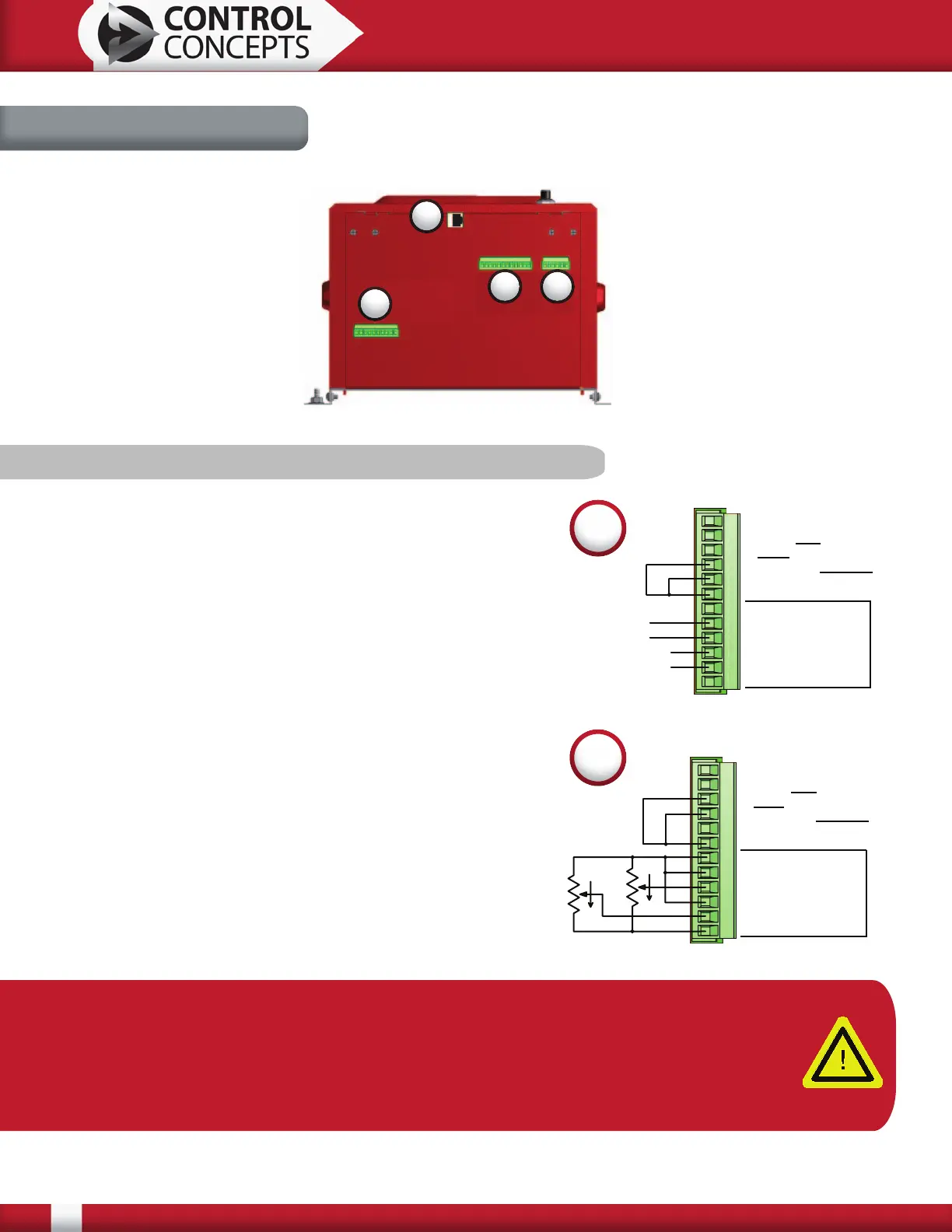
3.5.1 P1-12 Pin Command Connector
Diagram A, pictured right, shows SP1 setpoint with a 4/20
mA command and SP2 setpoint with a 0/5 Vdc command.
Connection A puts the controller in a digital setpoint mode.
Connection B places the controller in Run mode*.
Diagram B demonstrates how to hook up a potentiometer
input into SP1 setpoint and SP2 setpoint. Connection B
places the controller in Run mode*. Connection C selects
setpoint 2 as the command.
*Run/Reset has selectable open or closed logic to place the
controller in Run mode. The default value is closed. With
closed logic selected connection B must be connected to
place the controller in Run mode. Similarly with open logic
selected, remove the connection B to place the controller
in Run mode. Open/closed logic can be changed using the
FUSION Control Panel software. In the FUSION Control
Panel software there is also a digital Run/Reset enable
button. To place the controller in a Run state the digital
“Enable” button must be checked.
A
B
Note: The Compact FUSION power controller has two analog setpoints: SP1 and SP2.
On a single zone controller, either can be selected to control this zone.
On a 2 zone controller, SP1 is used to control zone 1 and SP2 is used to control zone
2. On controllers with more than 2 zones, a digital interface must be ordered for
communication with all zones.