23
© Control Concepts Inc., 2013
www.ccipower.com 1-800-765-2799
Compact FUSION Installation Manual Revision 3.50.2
3.5.2 External Feedback
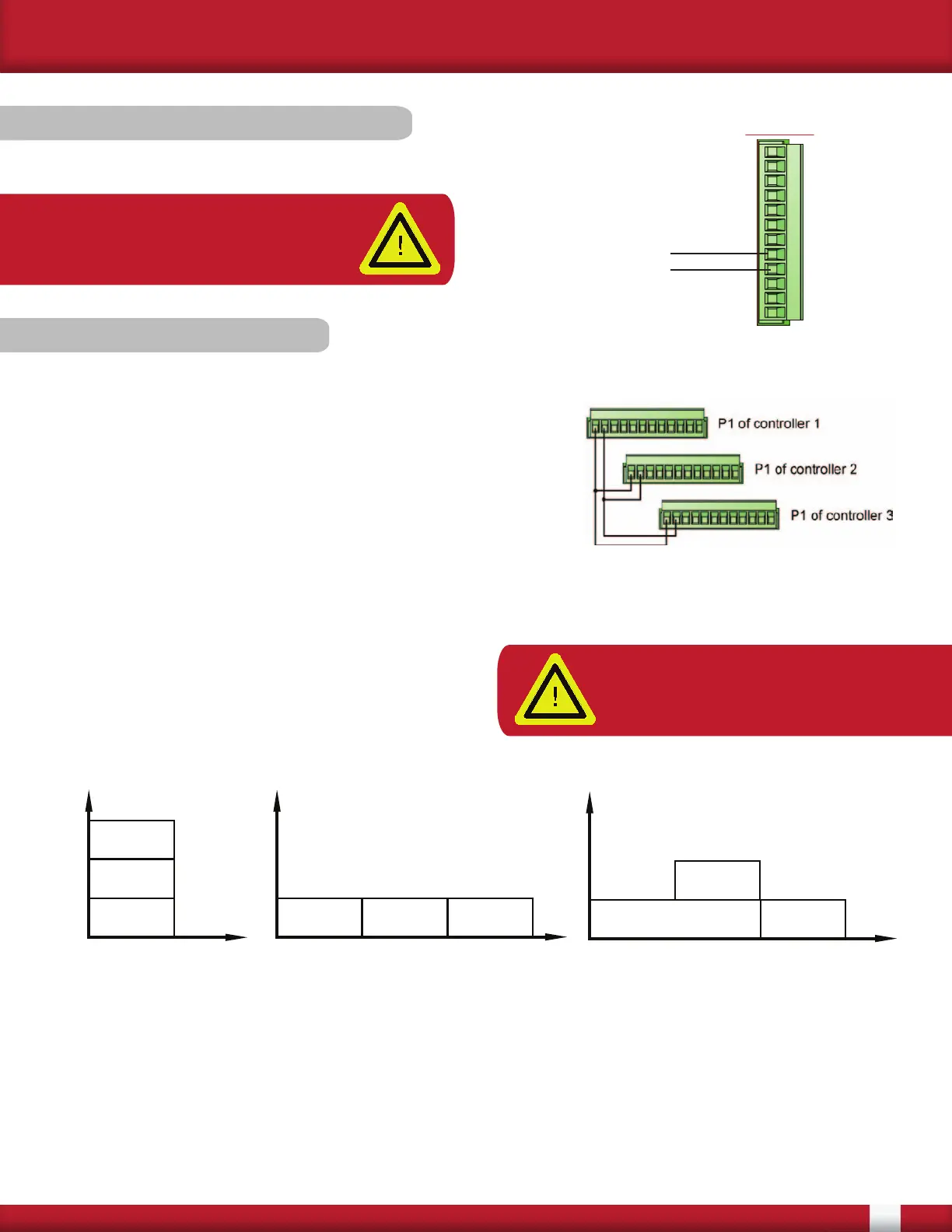
Connect the external feedback signal to pins 4 and 5 of the P1 (12-pin) connector.
5 (-) IN 2
4 (+) IN 2
Controller #1
ON
Controller #2
ON
Controller #3
ON
AMPS
TIME
Three controllers providing 33.3%
power each, with Sync-Guard™.
Controller #1
ON
Controller #2
ON
Controller #3
ON
AMPS
TIME
Three controllers with Sync-Guard™,
two providing 33.3% power and one
providing 66.6% power.
Controller #1
ON
Controller #2
ON
Controller #3
ON
AMPS
TIME
Three controllers providing
33.3% power each,
operating synchronously
(without Sync-Guard™).
Wiring of controllers for
SYNC-GUARD™ feature.
3.5.3 SYNC-GUARD™
The purpose of the SYNC-GUARD™ feature is to reduce
the possibility of synchronous operation of two or more Zero
Cross controllers. An explanation of use can be found in the
Operator Manual.
To set up the SYNC-GUARD™ feature, pins 11 and 12 of the
P1 connector have to be wired from one controller to another,
in parallel, as shown in the image to the right.
When using this feature, one and only one controller should have the SYNC-GUARD™ resistor
enabled via the Fusion Control Panel. See Fusion Control Panel software manual for more details.
The figures below show the total current as a
function of time for three controllers, with, and
without SYNC-GUARD™ and various load powers.
When using the SYNC-GUARD™ feature, the
command signals must be isolated from each other.
NOTE: A maximum of 10 controllers
regardless of the current rating can
be connected in this manner.
NOTE: Set up the external feedback
for the signal being used via the
FUSION Control Panel software