29
© Control Concepts Inc., 2013
www.ccipower.com 1-800-765-2799
Compact FUSION Installation Manual Revision 3.50.2
STEP
5
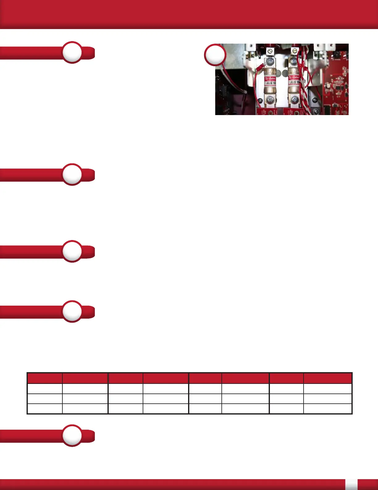
Once the circuit board is removed the fuse can
be replaced. In 10 - 50 Amp controllers there are
compression fit fuse blocks that hold the fuse. The
fuses can be easily replaced by removing the fuse
and installing the new one.
5
STEP
6
STEP
7
STEP
8
P1 Wire Color P2 Wire Color P14 Wire Color P15 Wire Color
G2 White/Yellow K1 Bus Red/Black G2 White/Yellow K1 Bus Red/Black
K2 SCR Red K1 SCR Red/Black K2 SCR Red K1 SCR Red/Black
K2 Bus Red G1 White K2 Bus Red G1 White
After verifying that all wiring has been connected correctly, the lids can be re-attached. Apply control
and line power to the controller. Verify that the blown fuse indicator is NOT present.
STEP
9
For controller sizes 80 - 160 Amps the fuses are held in by screws attached to insulators. Remove
the 2 screws holding down the fuse. Make note of the orientation of bus bars, wires and lugs when
removing the screws. In the case of a 80 Amp controller, the DVDT board needs to be removed from
the SCR in order to remove the bus bar attached to the fuse.
Apply a thin layer of penatrox A (or conductive anti-corrosive grease) to the fuse where it contacts
the lug and the bus bar. Replace the fuse and re-attach the Red wire with ring terminal and the lug.
Make sure that the lug is as close to the fuse as possible. The lug is should not touch the plastic wire
guides. For 80 Amp controllers torque the screws going into the SCR to 44 in/lbs. For all controllers
torque the screws, holding the fuse, to 75 in/lbs.
Re-insert the Gate Driver board. Secure the board with the 4 screws that were previously removed.
Connect all of the FFCs that were removed, starting with the shortest. If these were removed from
the Firing Card make sure to start with the lowest connector, working your way to the top.
Re-insert all of the previously removed wiring to the correct headers. Make sure to connect fan wires
if fans are present. The wiring that is the most critical to have correct are the Gate and Cathode leads
that are connected to the SCR. The connectors are P1, P2, P14 and P15. Verify that the colors are
correct with the following: