Menu 7
Parameter
structure
Keypad and
display
Parameter x.00
Parameter
description format
Advanced parameter
descriptions
Serial comms
protocol
Electronic
nameplate
Performance
106 Digitax ST Advanced User Guide
www.controltechniques.com Issue Number: 1
If an analog input is used with 4-20mA or 20-4mA current loop modes the respective bit (Pr 7.28 - analog input 2 and Pr 7.29 -analog input 3) is set to
one if the current falls below 3mA. If the current is above 3mA with these modes or another mode is selected the respective bit is set to zero.
An offset can be added to each analog input with a range from -100% to 100%. If the sum of the input and the offset exceeds ±100% the results is
limited to ±100%.
This offers a simple control of Pr 7.19 to change the source for the analog output for use from Menu 0. When this parameter is set to 0 or 1 the drive
constantly writes Pr 5.01 or Pr 4.02 to Pr 7.19 respectively.
The IGBT junction temperature displayed in this parameter is the sum of the power circuit 1 temperature (Pr 7.04) and a thermal model of the drive
power stage.
Pr 7.34 gives the IGBT junction temperature that would be produced after the delay taken to trip the drive or reduce the switching frequency if the
drive output current was increased to its maximum level. This means that Pr 7.34 may always show a temperature that is higher than the power circuit
1 temperature even when the drive is disabled. If the calculated IGBT temperature exceeds the levels shown in the table below the switching
frequency is reduced provided this feature has not been disabled (by setting Pr 5.35 to 1) or the minimum switching frequency has not been reached.
The switching frequency can be reduced from 12kHz to 6kHz to 3kHz, or from 8kHz to 4kHz. If this feature has been disabled (i.e. Pr 5.35 is one) or
the minimum switching frequency is reached the drive initiates an Oht1 trip. Once the switching frequency has been reduced the drive determines
when the switching frequency can be switched back up again.
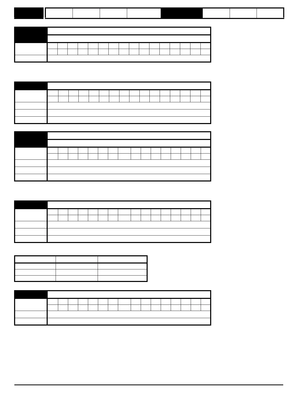
7.28 T7 analog input 2 current loop loss
7.29 T8 analog input 3 current loop loss
Coding
Bit SP FI DE Txt VM DP ND RA NC NV PT US RW BU PS
1111
Update rate Background write
7.30 T5/6 analog input 1 offset
Coding
Bit SP FI DE Txt VM DP ND RA NC NV PT US RW BU PS
211
Range ±100.00 %
Default 0.00
Update rate Background read
7.31 T7 analog input 2 offset
7.32 T8 analog input 3 offset
Coding
Bit SP FI DE Txt VM DP ND RA NC NV PT US RW BU PS
111
Range ±100.0 %
Default 0.0
Update rate Background read
7.33 T9 analog output 1 control
Coding
Bit SP FI DE Txt VM DP ND RA NC NV PT US RW BU PS
1 111
Range 0 to 2
Default 2
Update rate Background read
Parameter value Parameter string Action
0FrWrite Pr 7.19 = Pr 5.01
1LdWrite Pr 7.19 = Pr 4.02
2 AdV No action
7.34 IGBT junction temperature
Coding
Bit SP FI DE Txt VM DP ND RA NC NV PT US RW BU PS
111
Range ±200 °C
Update rate Background write