Parameter
structure
Keypad and
display
Parameter x.00
Parameter
description format
Advanced parameter
descriptions
Serial comms
protocol
Electronic
nameplate
Performance
Menu 7
Digitax ST Advanced User Guide 105
Issue Number: 1 www.controltechniques.com
In voltage mode the output range is -10V to 10V. If the scaling parameter is 1.000 then -10V and 10V are produced when the source parameter is at -
maximum and maximum respectively. Different scaling can be applied with Pr 7.23. If the result of the scaling produces an output of more than +/-
100% the output is clamped within the +/-10V range.
In current modes with a scaling parameter of 1.000 the minimum and maximum current are produced when the source parameter is at 0 and
maximum respectively. Therefore in 4 - 20mA mode the output is 4mA when the source parameter is zero. Different scaling can be applied with
Pr 7.23. If the result of the scaling produces an output of more than 100% the output is clamped at 20mA.
If high speed update mode is selected and the source for the output is one of the parameters designated for high speed analog output operation (see
start of this section) the output is updated at a higher rate with special scaling. If the parameter selected is not designated for this mode the output is
updated at the normal rate. If speed feedback or power is selected for high speed mode for both analog output 1 and analog output 2 the setting is
ignored for analog output 2. If the high speed mode is selected the output is always a voltage signal.
See Pr 7.21 T9 analog output 1 mode on page 104
Setting this bit will cause the drive to re-calibrate the full scale level of analog input 1 provided the input voltage is below +1.5V or above +2.5V. This
parameter is cleared by the software automatically when the calibration is complete. If the input voltage is above +2.5V the input voltage itself is used
for calibration, and so after calibration this level will be full scale for the input. If the input voltage is below +1.5V the internal reference is used for
calibration, and so the full scale will be nominally 9.8V after calibration. The calibration level is automatically stored on power-down. It should be noted
that the Analog input 1 offset trim is included in the input voltage when the input voltage itself is used for calibration, but this trim is not included when
the internal reference is used for calibration.
Analog input 1 is filtered using a window filter to remove quantization noise and adjust the resolution of this input. The length of the window can be
adjusted with this parameter. The shortest possible window is 250μs. It should be noted that if this input is not used as a speed reference (Pr 1.36,
Pr 1.37) or as a hard speed reference (Pr 3.22) the sample time affects the resolution. The nominal resolution is given by Pr 7.26 x 500 x 10, therefore
the default setting gives approximately 11 bit resolution.
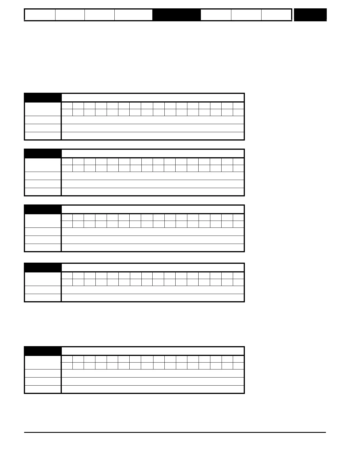
7.22 T10 analog output 2 source
Coding
Bit SP FI DE Txt VM DP ND RA NC NV PT US RW BU PS
2 1111
Range Pr 0.00 to Pr 21.51
Default Pr 4.02
Update rate Read on drive reset
7.23 T10 analog output 2 scaling
Coding
Bit SP FI DE Txt VM DP ND RA NC NV PT US RW BU PS
3111
Range 0.000 to 4.000
Default 1.000
Update rate Background read
7.24 T10 analog output 2 mode
Coding
Bit SP FI DE Txt VM DP ND RA NC NV PT US RW BU PS
1 111
Range 0 to 3
Default 0
Update rate Background read
7.25 Calibrate T5/6 analog input 1 full scale
Coding
Bit SP FI DE Txt VM DP ND RA NC NV PT US RW BU PS
111
Default 0
Update rate Background read
7.26 T5/6 analog input 1 sample time
Coding
Bit SP FI DE Txt VM DP ND RA NC NV PT US RW BU PS
1111
Range 0 to 8.0 ms
Default 4.0
Update rate Background read