Menu 21
Parameter
structure
Keypad and
display
Parameter x.00
Parameter
description format
Advanced parameter
descriptions
Serial comms
protocol
Electronic
nameplate
Performance
206 Digitax ST Advanced User Guide
www.controltechniques.com Issue Number: 1
0, drv: Drive encoder
The position feedback from the encoder connected to the drive itself is used to derive the speed feedback for the speed controller and to calculate the
motor rotor flux position.
1, Slot1: Solutions Module in slot 1
The position feedback from the Solutions Module in Solutions Module slot 1 is used to derive the speed feedback for the speed controller and to
calculate the motor rotor flux position. If a position feedback category Solutions Module is not installed in slot 1 the drive produces an EnC9 trip.
2, Slot2: Solutions Module in slot 2
3, Slot3: Solutions Module in slot 3
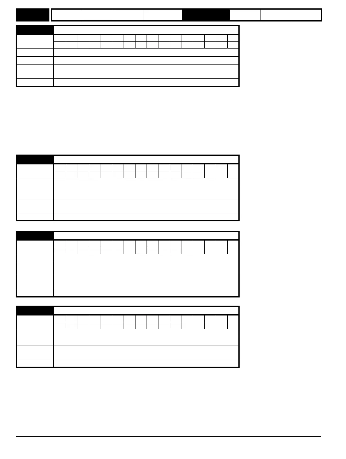
21.21 Speed feedback selector
Coding
Bit SP FI DE Txt VM DP ND RA NC NV PT US RW BU PS
1111
Range 0 to 3
Default 0
Normal motor
parameter
Pr 3.26
Update rate Background read
21.22 Current controller Kp gain
Coding
Bit SP FI DE Txt VM DP ND RA NC NV PT US RW BU PS
111
Range 0 to 30,000
Default
200V drive: 75
400V drive: 150
Normal
parameter
Pr 4.13
Update rate Background read
21.23 Current controller Ki gain
Coding
Bit SP FI DE Txt VM DP ND RA NC NV PT US RW BU PS
111
Range 0 to 30,000
Default
200V drive: 1,000
400V drive: 2,000
Normal
parameter
Pr 4.14
Update rate Background read
21.27 Motoring current limit
Coding
Bit SP FI DE Txt VM DP ND RA NC NV PT US RW BU PS
11 1 111
Range 0 to MOTOR2_CURRENT_LIMIT_MAX %
Default 300.0
Normal
parameter
Pr 4.05
Update rate Background read