Parameter
structure
Keypad and
display
Parameter x.00
Parameter
description format
Advanced parameter
descriptions
Serial comms
protocol
Electronic
nameplate
Performance
Menu 3
Digitax ST Advanced User Guide 55
Issue Number: 1 www.controltechniques.com
Although Pr 3.35 can be set to any value from 0 to 32, if the value is less than 1, the resolution is 1 bit. Some SSI encoders (SC.SSI or SSI) include a
power supply monitor alarm using the least significant bit of the position. It is possible for the drive to monitor this bit and produce an EnC6 trip if the
power supply is too low (see Pr 3.40). If the encoder gives this information the comms resolution should be set up to include this bit whether it is being
monitored by the drive or not. It should be noted that some SSI encoders include trailing zeros after the position. This parameter should be set up to
include the trailing zero bits.
It is possible for the drive to set up this parameter automatically from information obtained from the encoder via Hiperface or EnDat interfaces (see
Pr 3.41).
The encoder supply voltage present on the drive encoder connector is defined by this parameter as 0 (5V), 1 (8V), or 2 (15V).
This parameter defines the baud rate for the encoder comms when using SSI or EnDat encoders. However, a fixed baud rate of 9600 baud is used
with HIPERFACE encoders and this parameter has no effect.
Any baud rate can be used when encoder comms is used with a SINCOS encoder to obtain the absolute position during initialisation. When encoder
comms is used alone (EnDat or SSI selected with Pr 3.38) the time taken to obtain the comms position must be 160μs or less, otherwise the drive
initiates an EnC4 trip.
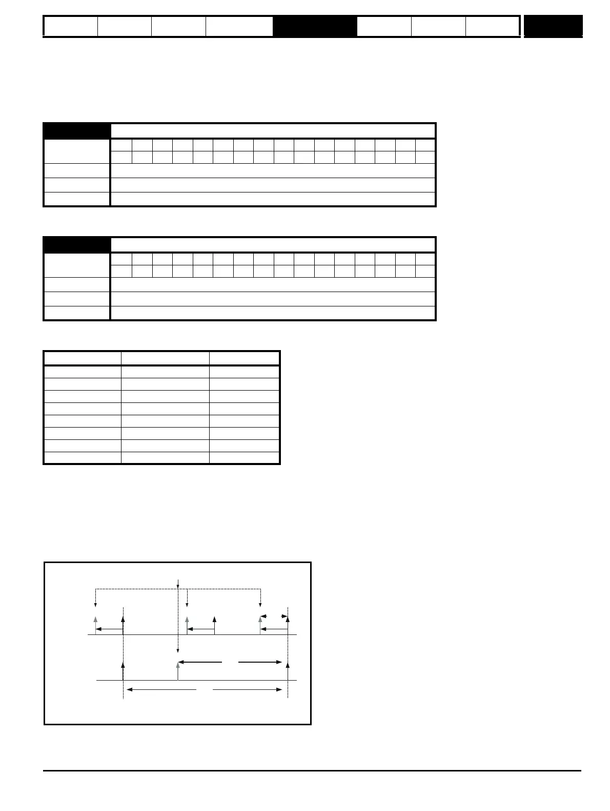
There is a delay obtaining the position from an encoder using comms alone. The length of this delay affects the sample rate and timing of the position
used by the drive for control and the position passed to Solutions Modules. If for an EnDat encoder the position within one turn can be obtained in
30μs and the whole comms message including CRC can be obtained in 60μs then fast sampling is used, otherwise slow sampling is used as shown
below. If for an SSI encoder the whole position can be obtained in 30μs fast sampling is used. In each case the position is sampled within the encoder
at the start of the comms message from the drive.
3.36
Drive encoder supply voltage
Coding
Bit SP FI DE Txt VM DP ND RA NC NV PT US RW BU PS
1 111
Range 0 to 2
Default 0
Update rate Background read
3.37
Drive encoder comms baud rate
Coding
Bit SP FI DE Txt VM DP ND RA NC NV PT US RW BU PS
1 111
Range 0 to 7
Default 2
Update rate Background read (Only has any effect when the drive is disabled)
Parameter value Parameter string Baud rate
0 100 100k
1 200 200k
2 300 300k
3 400 400k
4 500 500k
5 1000 1M
6 1500 1.5M
7 2000 2M
Slow
Sampling
Fast
Sampling
250 s
μ
Datum
Point
Datum
Point
150 s
μ
20 s
μ
Start of comms messages and encoder position sampling point