Menu 3
Parameter
structure
Keypad and
display
Parameter x.00
Parameter
description format
Advanced parameter
descriptions
Serial comms
protocol
Electronic
nameplate
Performance
54 Digitax ST Advanced User Guide
www.controltechniques.com Issue Number: 1
The equivalent number of encoder lines per revolution (ELPR) is defined as follows.
For any type of linear encoder one revolution is the motor pole pitch multiplied by the number of poles set up in Pr 5.11 or Pr 21.11.
Ab.Servo, Fd.Servo, Fr.Servo
The incremental (A/B) signal frequency should not exceed 500kHz.
It should be noted that if this parameter is set to zero the incremental signals are ignored and only the UVW commutation signals are used to define
the motor position. See Pr 3.38. If Pr 3.34 or the motor pole pairs defined by either Pr 5.11 or Pr 21.11 (depending on the motor map selected) are
modified and the encoder type is Ab.Servo, Fd.Servo or Fr.Servo then encoder is re-initialized. This ensures that the control position used by the drive
to determine the flux axis of the motor is re-aligned with the commutation signals when the encoder moves again and prevents possible errors.
SC.Hiper, SC.EnDat, SC, SC.SSI
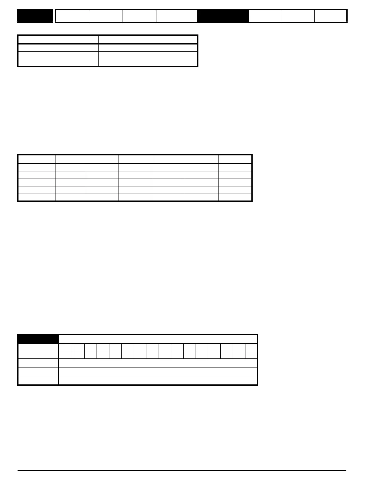
The sine wave signal frequency can be up to 500kHz, but the resolution is reduced at higher frequencies. The table below shows the number of bits
of interpolated information at different frequencies and with different voltage levels at the drive encoder port. The total resolution in bits per revolution
is the ELPR plus the number of bits of interpolated information. Although it is possible to obtain 11 bits of interpolation information, the nominal design
value is 10 bits.
If the position feedback device is a rotary SINCOS encoder with comms the position supplied via comms gives a number of counts per revolution that
is a power of two and the resolution is defined by the single turns comms bit (Pr 3.35). It is assumed therefore that the number of periods per
revolution is also a power of two, and so if a SC.Hiper, SC.EnDat or SC.SSI type devices is selected and Pr 3.39 is 1 or 2 to select a rotary encoder =
1 or 2, Pr 3.34 is forced to be a power of two between 2 and 32768.
When Pr 3.34 is adjusted an EnC7 trip is produced, because the encoder requires re-initialisation. If this parameter is set to a value that is not a
power of two and the encoder is set up as a linear encoder (Pr 3.39 = 0) the sample rate for the current controllers is reduced to 6kHz for 6 or 12kHz
switching frequency. All other switching frequencies are unaffected. See Pr 5.37 on page 87.
If the position feedback device is SC.Hiper or SC.EnDat it is possible for the drive to set up this parameter automatically from information obtained
from the encoder (see Pr 3.41 on page 60).
EnDat, SSI
Where encoder comms alone is used as position feedback, the equivalent lines per revolution (Pr 3.34) is not used in setting up the encoder interface.
If auto-configuration is used (see Pr 3.41 on page 60), then Pr 3.41 is set to zero if this is successful.
Linear motors
The value entered in this parameter for a linear motor should be calculated as follows:
If this value is not an integer then an SM-Universal Encoder Plus is required.
Ab, Fd, Fr, Ab.Servo, Fd.Servo, Fr.Servo, SC
Pr 3.35 defines the marker mode. If this parameter is zero the marker system operates in a conventional manner, but if this parameter is non-zero the
marker causes a full position reset.
SC.Hiper, SC.EnDat, SC.SSI and 03.39 = 1 or 2 (Rotary encoder)
Pr 3.35
must be set to the number of comms bits used to represent one revolution of the encoder. The single turn comms resolution may be higher
than the resolution of the sine waves per revolution.
SC.Hiper, SC.EnDat, SC.SSI and 03.39 = 0 (Linear encoder)
Pr 3.35 must be set up to the total number of bits representing the whole encoder position in the comms message. This parameter is not used with
linear SC.Hiper encoders as the number of bits used to represent the whole position is always 32.
EnDat, SSI
Pr 3.35 must be set to the number of bits used to represent one revolution of the encoder.
Position feedback device ELPR
Ab, Ab.Servo number of lines per revolution
Fd, Fr, Fd.Servo, Fr.Servo number of lines per revolution / 2
SC.Hiper, SC.EnDat, SC, SC.SSI number of sine wave periods per revolution
Volt/Freq 1kHz 5kHz 50kHz 100kHz 200kHz 500kHz
1.2 11 11 10 10 9 8
1.0111110997
0.8101010987
0.610109987
0.4999876
3.35
Drive encoder single turn comms bits / Linear encoder comms bits/Marker mode
Coding
Bit SP FI DE Txt VM DP ND RA NC NV PT US RW BU PS
111
Range 0 to 32 bits
Default 0
Update rate Background read (Only has any effect when the drive is disabled)
Pr 3.34 PPR setting
Motor pole pitch
Encoder pitch 4×()
------------------------------------------------------=