Menu 3
Parameter
structure
Keypad and
display
Parameter x.00
Parameter
description format
Advanced parameter
descriptions
Serial comms
protocol
Electronic
nameplate
Performance
60 Digitax ST Advanced User Guide
www.controltechniques.com Issue Number: 1
Wire-break detection
It may be important to detect a break in the connections between the drive and the position feedback device. This feature is provided for most
encoder types either directly or indirectly as listed below.
Encoder initialisation
Encoder initialisation will occur as follows: at drive power-up, when requested by the user via Pr 3.47, when trips PS.24V or EnC1 to EnC8 or Enc11
to Enc17 are reset. Initialisation causes an encoder with comms to be re-initialized and auto-configuration to be performed if selected. After
initialisation Ab.Servo, Fd.Servo and Fr.Servo encoders will use the UVW commutations signals to give position feedback for the first 120deg
(electrical) of rotation when the motor is restarted.
A delay is provided during initialisation for some encoders to allow the encoder to be ready to provide position information after it has powered up.
The delay is provided during initialisation because this occurs during drive power-up and after encoder power supply trips are reset. The delays are as
follows:
Encoder power supply trips
The encoder power supply from the drive can be switched off by the drive either because the encoder power supply is overloaded (EnC1 trip) or
because the internal 24V supply within the drive is overloaded (PS.24V trip). The internal 24V supply provides power for the encoder power supply,
user 24V output, digital I/O, Solutions Modules etc. To ensure that an EnC1 trip is not initiated when the internal 24V is overloaded, and subsequently
switched off by the drive, there is a delay of 40ms in the detection of EnC1 trip. It is possible for other encoder trips such as wire break detection
(EnC2) to occur when the power supply is removed from the encoder. Therefore overloading the internal 24V supply or the encoder supply could
result in an immediate EnC2 trip. To ensure that the correct reason for the trip is given PS.24V and EnC1 trips override an existing EnC2 to EnC8 or
Enc11 trip. This means that both the original trip (EnC2 to EnC8 or Enc11) and then the new trip (PS.24V or EnC1) are stored in the trip log.
SC.Hiper, SC.EnDat, EnDat
When a SC.Hiper, SC.EnDat or EnDat encoder is being used, the drive will interrogate the encoder on power-up. If Pr 3.41 is set to one and the
encoder type is recognized based on the information provided by the encoder, the drive will set the encoder turns / linear encoder comms to sine
wave ratio (Pr 3.33), the equivalent lines per revolution (Pr 3.34) and the encoder comms resolution / linear encoder comms bits (Pr 3.35). For
SC.Hiper or SC.EnDat encoders the rotary encoder select (Pr 3.39) is also set up. If the encoder is not recognized, there is a comms error or the
resulting parameter values are out of range the drive initiates an EnC7 or Enc12 to Enc17 trip to prompt the user to enter the information. The drive
can auto-configure with any of the following devices.
Rotary EnDat encoders
The encoder turns, comms resolution and equivalent lines per rev are set up directly using the data read from the encoder.
Device Detection method Drive Trip
Ab, Fd, Fr, Ab.Servo,
Fd.Servo, Fr.Servo
Hardware detectors on the A(F), B(D,R) and Z signal detect a wire
break.
EnC2
SC,
SC.Hiper,
SC.EnData,
SC.SSI
The differential levels of the sine and cosine waveforms are
available to the drive. The drive detects wire break if Sine
2
+Cosine
2
is less than the value produced by two valid waveforms with a
differential peak to peak magnitude of 0.25V (1/4 of the nominal
level). This detects wire break in the sine and cosine connections.
EnC2
SC.Hiper, SC.EnDat, EnDat
Wire break in the comms jumper (link) is detected by a CRC or
timeout error.
EnC4, EnC5
SSI
Wire break detection is difficult with these devices. However, if
power supply monitoring is enabled the drive will be looking for a
one at the start of the message and a zero to indicate that the power
supply is okay. If the clock stops or the data line is disconnected the
data input to the drive may stay in one state or the other and cause a
trip.
EnC5, EnC6
Encoder type Initialisation delay
Ab, Fd, Fr, Ab.Servo,
Fd.Servo, Fr.Servo
None
SC.Hiper 150ms, then encoder reset, then 150ms
SC.EnDat, EnDat 1.0s
All other types 1.2s
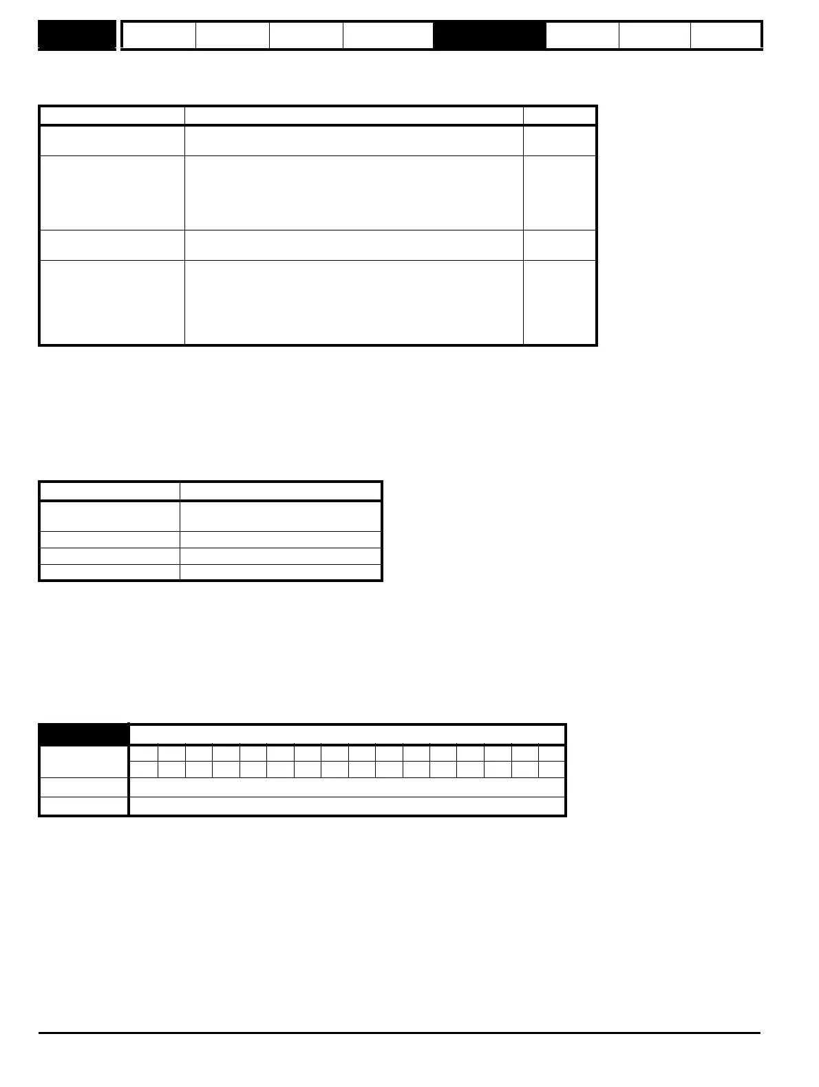
3.41
Drive encoder auto configuration enable / SSI binary format select
Coding
Bit SP FI DE Txt VM DP ND RA NC NV PT US RW BU PS
1 111
Default 0
Update rate Background read