Parameter
structure
Keypad and
display
Parameter x.00
Parameter
description format
Advanced parameter
descriptions
Serial comms
protocol
Electronic
nameplate
Performance
Menu 4
Digitax ST Advanced User Guide 69
Issue Number: 1 www.controltechniques.com
Example:
Work out the available current limit for a DST1405 with a motor rated current of 8A set in Pr 5.07 (i.e. equal to the Maximum current rating of the
drive).
From Table 5-3 above the Current scaling (Kc) value for a DST1405 is 13.72A.
If the motor rated current is reduced then the maximum available current limit increases up to a maximum of 1000%.
The drive only requires the motor rated current to set the maximum current limit correctly and scale the current limits, and so no auto-tuning is
required to set these accurately.
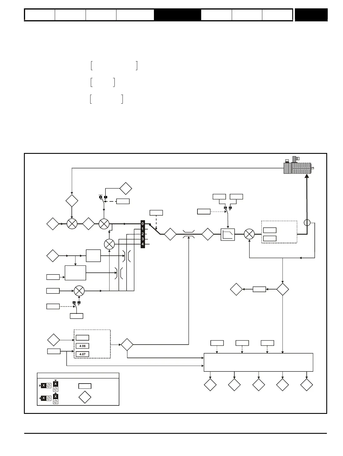
Figure 5-4 Menu 4 Logic diagram
CURRENT_LIMIT_MAX
Maximum current
Motor rated current
-------------------------------------------------------
100%×=
1.75 x Kc
8A
--------------------------
100%×=
1.75 x 17.32A
8A
-------------------------------------
100%×=
4.18
11.32
5.07
4.05
Motoring
Regenerating
Current limits
Symmetrical
Drive rated
continuous
current
Motor rated
current
Over-riding
current limit
3.05
Zero
speed
threshold
Torque reference
offset
Torque
reference*
Speed
over-ride
level
Coiler/uncoiler
speed
over-ride
level
+
At 100%
load
Current limit
active
indicator
Motor active
current
selector
4.11
4.10
Torq ue
reference
offset
enable
+
+
+
4.03
Torque
demand
0.XX
0.XX
Key
Read-write (RW)
parameter
Read-only (RO)
parameter
Input
terminals
Output
terminals
Percentage
load
The parameters are all shown at their default settings
4.23
Current
demand
filter 1
4.12
Current
demand
filter 2
User current
max scaling
Speed controller
gain select
3.16
1.03
Pre-
ramp
reference
3.04
+
3.01
3.02
Speed
feedback
Final
speed
demand
_
Speed loop
output
+
+
4.22
2.38
Inertia
compensation
enable
+
Inertia
compensation
torque