Parameter
structure
Keypad and
display
Parameter x.00
Parameter
description format
Advanced parameter
descriptions
Serial comms
protocol
Electronic
nameplate
Performance
Menu 5
Digitax ST Advanced User Guide 85
Issue Number: 1 www.controltechniques.com
A suitable field controller gain is automatically set by the drive from the motor parameters. However it is possible by setting this parameter to a 1 to
reduce this gain by a factor of 2 if instability problems occur above base speed.
High speed servo mode is not enabled as default. Care must be taken when using this mode with servo motors to avoid damaging the drive. The
voltage produced by the servo motor magnets is proportional to speed. For high speed operation the drive must apply currents to the motor to
counter-act the flux produced by the magnets. It is possible to operate the motor at very high speeds that would give a very high motor terminal
voltage, but this voltage is prevented by the action of the drive. If however, the drive is disabled (or tripped) when the motor voltages would be higher
than the rating of the drive without the currents to counter-act the flux from the magnets, it is possible to damage the drive. If high speed mode is
enabled the motor speed must be limited to the levels given in the table below unless an additional hardware protection system is used to limit the
voltages applied to the drive output terminals to a safe level.
Ke is the ratio between r.m.s. line to line voltage produced by the motor and the speed in V/1000rpm. Care must also be taken not to de-magnetize
the motor. The motor manufacturer should always be consulted before using this mode.
The transient inductance is the phase inductance for a servo motor. This is half the inductance measured from phase to phase. This value is used for
cross-coupling compensation and to set the current controller gains.
When this bit is set the drive provides a cross-coupling feed forward voltage as produced by the transient inductance and a frequency based voltage
feed forward term. These voltages improve the transient performance of the current controllers.
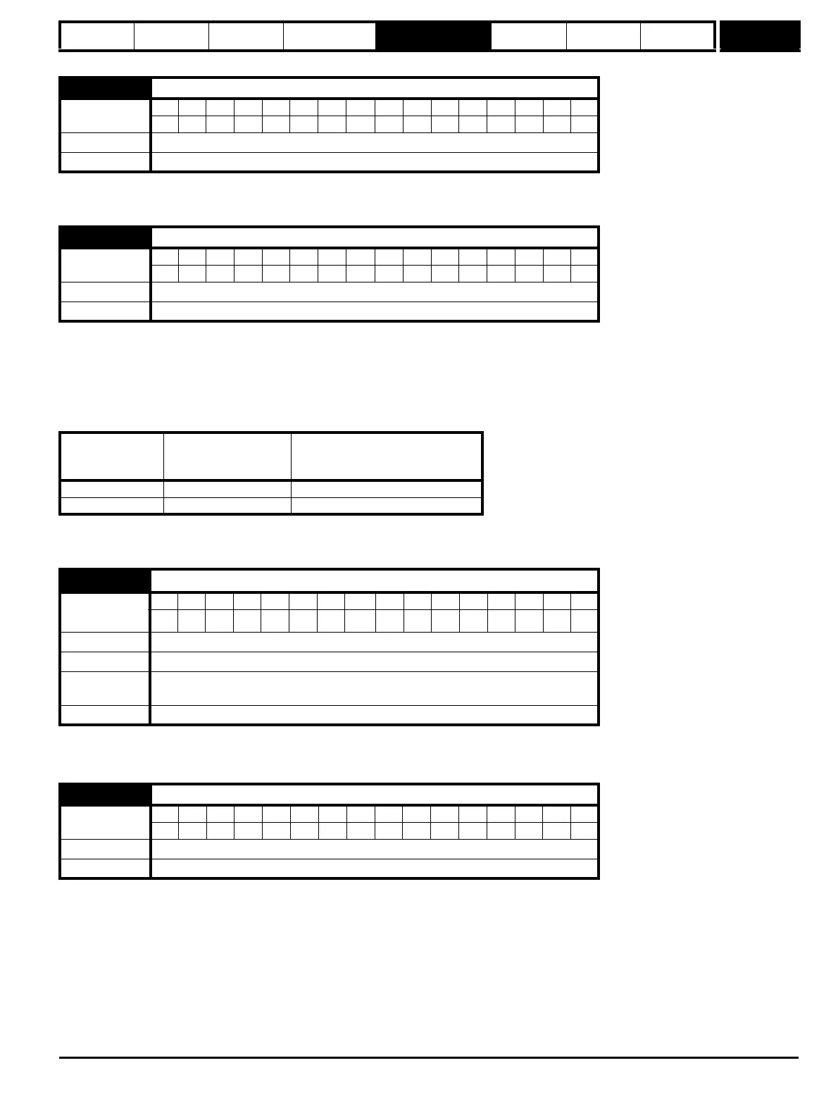
5.21 Field gain reduction
Coding
Bit SP FI DE Txt VM DP ND RA NC NV PT US RW BU PS
111
Default 0
Update rate Background read
5.22 Enable high speed servo mode
Coding
Bit SP FI DE Txt VM DP ND RA NC NV PT US RW BU PS
111
Default 0
Update rate Background read
Drive voltage
rating
Maximum motor
speed
(rpm)
Maximum safe line to line voltage
at the motor terminals (V rms)
200 400 x 1000 / (Ke x √2) 400 / √2
400 800 x 1000 / (Ke x √2) 800 / √2
5.24
Transient inductance (σL
s
)
Coding
Bit SP FI DE Txt VM DP ND RA NC NV PT US RW BU PS
31 111
Range 0.000 to 500.000 mH
Default 0.000
Second motor
parameter
Pr 21.14
Update rate Background read
5.26 High dynamic performance enable
Coding
Bit SP FI DE Txt VM DP ND RA NC NV PT US RW BU PS
111
Default 0
Update rate Background read