Menu 5
Parameter
structure
Keypad and
display
Parameter x.00
Parameter
description format
Advanced parameter
descriptions
Serial comms
protocol
Electronic
nameplate
Performance
84 Digitax ST Advanced User Guide
www.controltechniques.com Issue Number: 1
This parameter defines the action taken on enable as follows:
0: nonE
No action.
1: Ph Enl
A minimal movement phasing test is performed each time the drive is enabled (i.e. changes from the inhibit state to either the stop or run state). The
test can be used to determine the phasing angle for an absolute or non-absolute type encoder. If the test is completed successfully the drive changes
to the stop or run state as appropriate. The phasing angle parameter is updated to the correct value, but it is not saved to EEPROM or the
SMARTCARD.
2: Ph Init
A minimal movement phasing test is performed the first time the drive is enabled after power-up. The test will only be performed again on enable if the
position feedback device(s) have been re-initialized. Re-initialisation occurs for example after a trip specifically related to an encoder where position
information may have been lost. Initialisation occurs when Pr 3.48 changes from zero to one. The phasing angle parameter is updated to the correct
value, but it is not saved to EEPROM or the SMARTCARD.
Pr 5.17 shows the stator resistance of the motor divided by 10. Therefore 1.000 in this parameter represents the resistance of 10 Ohms.
This parameter defines the required switching frequency. The drive may automatically reduce the actual switching frequency (without changing this
parameter) if the power stage becomes too hot. The switching frequency can reduce from 12kHz to 6kHz to 3kHz, or 8kHz to 4kHz. An estimate of the
IGBT junction temperature is made based on the heatsink temperature and an instantaneous temperature drop using the drive output current and
switching frequency. The estimated IGBT junction temperature is displayed in Pr 7.34. Reducing the switching frequency reduces the drive losses
and the junction temperature displayed in Pr 7.34 also reduces. If the load condition persists the junction temperature may continue to rise. If the
temperature exceeds the values given in the description for Pr 7.34 on page 106, and the switching frequency cannot be reduced, the drive will initiate
an O.ht1 trip (see Pr 5.35 on page 86 and Pr 7.34 on page 106). Every 20ms the drive will attempt to restore the switching frequency if the higher
switching frequency will not take the IGBT temperature above 135°C. The following table gives the sampling rate for different sections of the control
system for different switching frequencies.
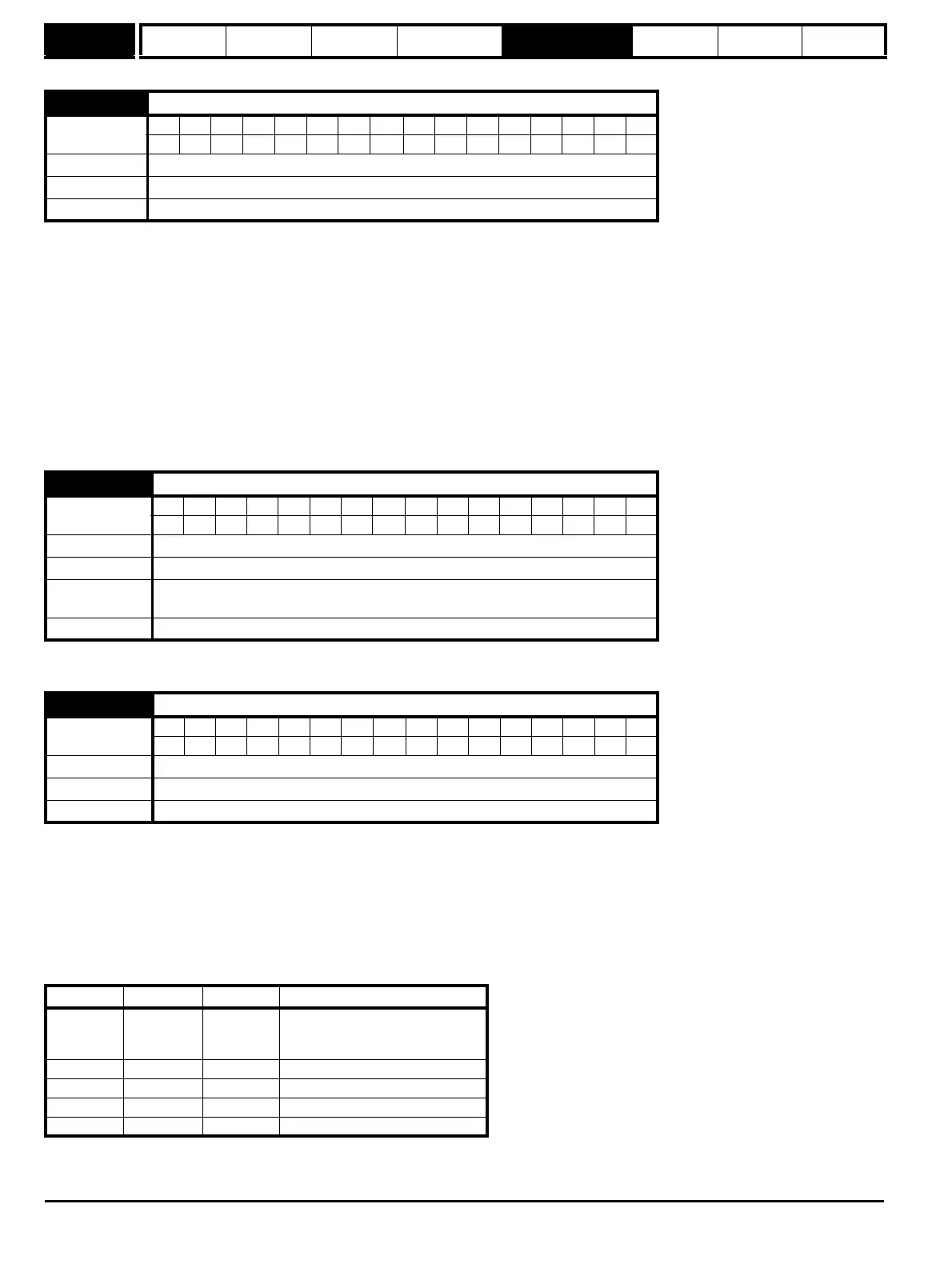
5.14 Action on enable
Coding
Bit SP FI DE TE VM DP ND RA NC NV PT US RW BU PS
1 111
Range 0 to 2
Default 0
Update rate Background read
5.17 Stator resistance
Coding
Bit SP FI DE Txt VM DP ND RA NC NV PT US RW BU PS
3 1 111
Range 0.000 to 65.000 x 10Ω
Default 0.000
Second motor
parameter
Pr 21.12
Update rate Background read
5.18 Maximum switching frequency
Coding
Bit SP FI DE Txt VM DP ND RA NC NV PT US RW BU PS
1 1 111
Range 0 to 4 (3, 4, 6, 8, 12kHz)
Default 2 (6 kHz)
Update rate Background read
3, 6, 12kHz 4, 8kHz Control system
Level 1
3 = 167μs
6 = 83μs
12 = 83μs
125μs Current controllers
Level 2 250μs 250μs Speed controller and ramps
Level 3 1ms 1ms Voltage controller
Level 4 4ms 4ms Time critical user interface
Background N/A N/A Non-time critical user interface