QUICK‐FITGSM
INSTALLATIONMANUAL
Page17
Example:
DTMF combination Description
00 Deactivate ALL outputs
01 Activate ALL outputs
11 Activate output 1
20 Deactivate output 2
Table 5: DTMF control example
9.2 OUTPUT MANAGEMENT
QUICK-FIT GSM supports the possibility to report alarms from inputs and any other
events locally via 4 outputs. The behavior is defined using next parameters
9.2.1 OS parameter
QUICK-FIT GSM device has 2 dedicated relay and 2 OC transistor supported outputs.
Outputs can be configured to different behavior:
⇒ OS = 0 – Disabled
⇒ OS = 1 – Bi-stable toggle mode
⇒ OS = xxx – Mono-stable pulse mode ( any duration in seconds )
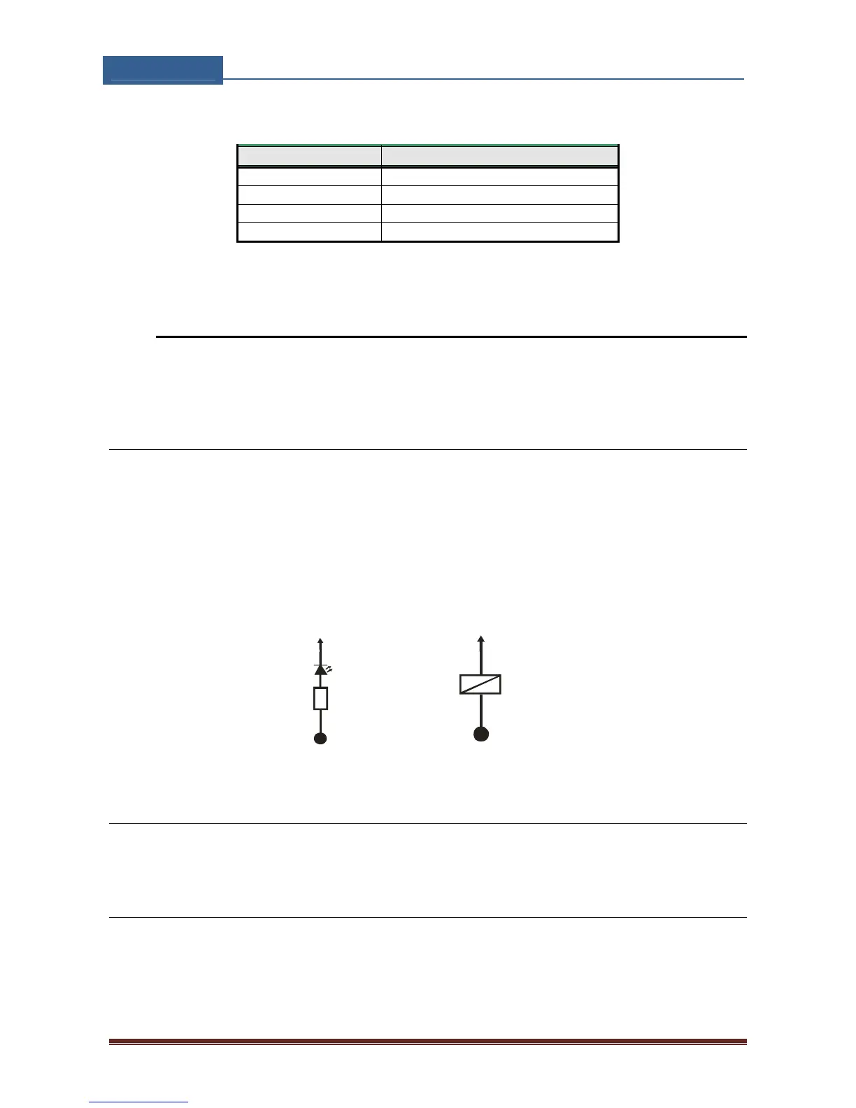
Typical connection for the output:
+12V DC
OUTPUT 1-4
R 1K
LED
+12V DC
1-4OUTPUT
RELAY
12V DC
Figure 3: Output Connection diagram
9.2.2 OD parameter
OD parameter is used to link the alarm event directly to output.
9.2.3 OP1, OP2 parameters
Parameters are used to invert the polarity of the outputs.
⇒ 0 – normal (N/O)
⇒ 1 – inverted (N/C)