95
Installation Instructions for:
Shop Unit Monitor CSUM355
Cooper Fire Systems
Tel: +44 (0) 1594 541900
Fax: +44 (0) 1594 541910
.PINSTCSUM3 55
Installation
1. Separate the two halves of the unit.
2. Drill out (or knock out) the required cable entries in the surface mounting back-box.
3. Fit the back-box in position and pass the wires into it.
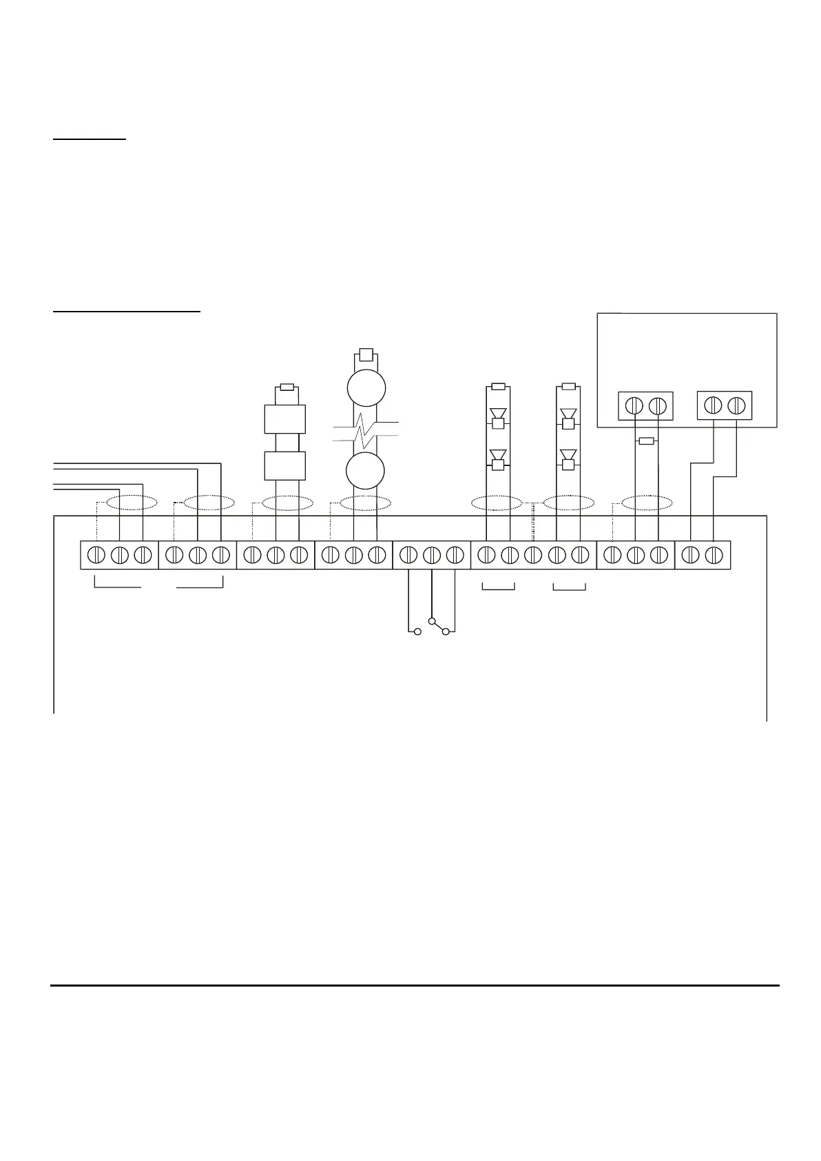
4. Connect the unit according to the diagram below.
Notes:
No addressing of the interface is required. See control panel operation for details.
Standard Connections
E
LOOP
OUT
IN
CALL
POINT
ZONE
DETECTOR
ZONE
SOUNDER
EXTERNAL
PSU
MONITOR
24V
EXTERNAL
PSU
INPUT
2
1
FIRE
RELAY
E
EE
E
E
N/O
Fault
Contact
N/O
24V DC OUTPUT
POWER SUPPLY UNIT
24V
O/P
C
N/C
-
-
--
+
+++
-
+
-
-
+
+
-
+
-
-
+
+
- OUT +
- IN +
- OUT +
- IN +
12K
12K
6K8
12K
EOLM-1
Analogue Addressable Loop
Maximum 20
Conventional
Detectors
Notes:
1. This unit can only be used with Cooper 300 series detector base and compatible detectors.
2. Only connect cable screen to its adjacent earth terminal.
3. The end of line resistor must always be fitted, even if the spur is unused.
4. Maximum spur length – See BS5839 Pt1:2001 for Zone Coverage.
5. Maximum number of call points allowed is unlimited.
6. Detector zone end of line device is EOLM-1