Installation/removal
Cornelius Deutschland GmbH
Document no. TD2005100
Version 15/03/2019, Index 0
Installation and service manual Dispensing valve
SFV1
9
4 Installation/removal
DANGER!
Risk of personal injury and equipment damage due to non-compliance with safety information!
If you fail to observe the safety information, you risk creating operating conditions at the dispensing valve which
may cause personal injury or damage to equipment.
• Please always strictly observe all safety measures and information/instructions, see chapter 1.
NOTICE!
All installation, maintenance and repair work on the dispensing valve must be carried out by an expert only.
WARNING!
Risk of personal injury and equipment damage due to operation by non-qualified staff!
It is dangerous for non-qualified staff to operate the unit!
• Service operations on the dispensing valve may only be carried out by trained and certified experts who
have been trained in undertaking service operations on the dispensing valve.
• All wiring and plumbing must be carried out in compliance with national and local laws, regulations and
guidelines. Non-compliance with these laws, regulations and guidelines may result in death, serious injury
or equipment damage.
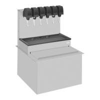
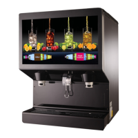
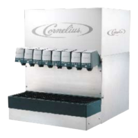
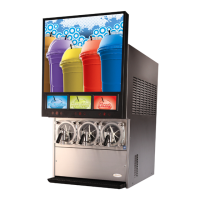
The dispensing valve SFV1 is suitable for installation on various base units (overcounter cooler or tower).
The dispensing valve SFV1 is attached to the dispensing valve support via the block mount.
Each base unit has an almost identical dispensing valve support. Installation is described here analogously using an example.
4.1 Installing the dispensing valve
Prerequisites References
The dispensing valve has been unpacked. See the document “Dispensing valve operator manual”, docu-
ment no.: TD2005000
The front valve cover has been removed. see chapter 6.1
The rear valve cover has been removed. see chapter 6.2
The base unit has been installed correctly. See base unit documentation
The base unit has been shut down. See base unit documentation
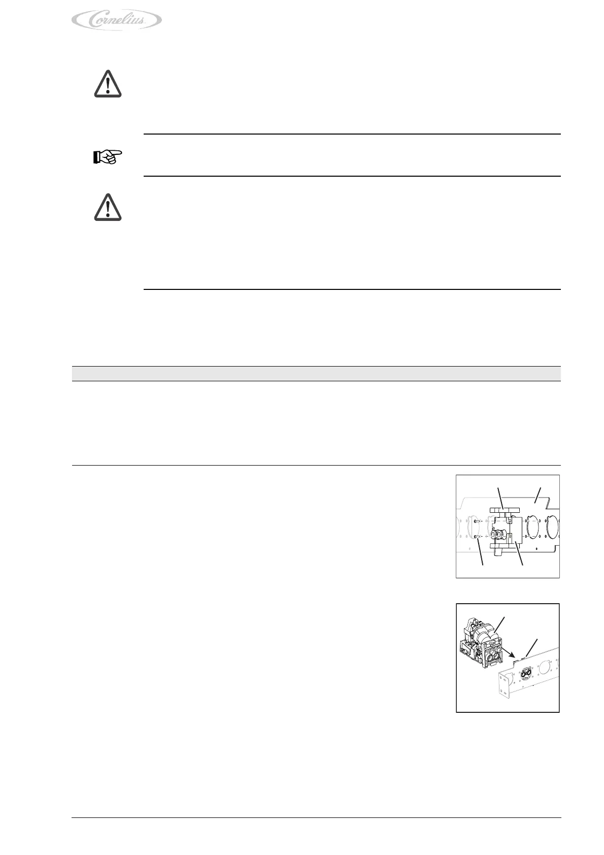
1. Position the block mount (Fig. 5/3) on the dispensing valve support (Fig. 5/2).
2. Attach the block mount (Fig. 5/3) to the dispensing valve support (Fig. 5/2) using the fastening
bolts (Fig. 5/4).
Fig. 5
21
34
3. Attach the dispensing valve (Fig. 6/1) to the block mount (Fig. 6/2) by pressing the dispensing
valve (Fig. 6/1) onto the block mount (Fig. 6/2).
4. Lock the block mount (Fig. 6/2) by pressing the locking mechanism (Fig. 5/1) downwards.
Finishing tasks
1. Mount the rear valve cover, see chapter 6.2.
2. Mount the front valve cover, see chapter 6.1.
3. Start up the base unit, see base unit documentation.
Fig. 6
1
2