Installation/removal
Cornelius Deutschland GmbH
Document no. TD2005100
Version 15/03/2019, Index 0
Installation and service manual Dispensing valve
SFV1
10
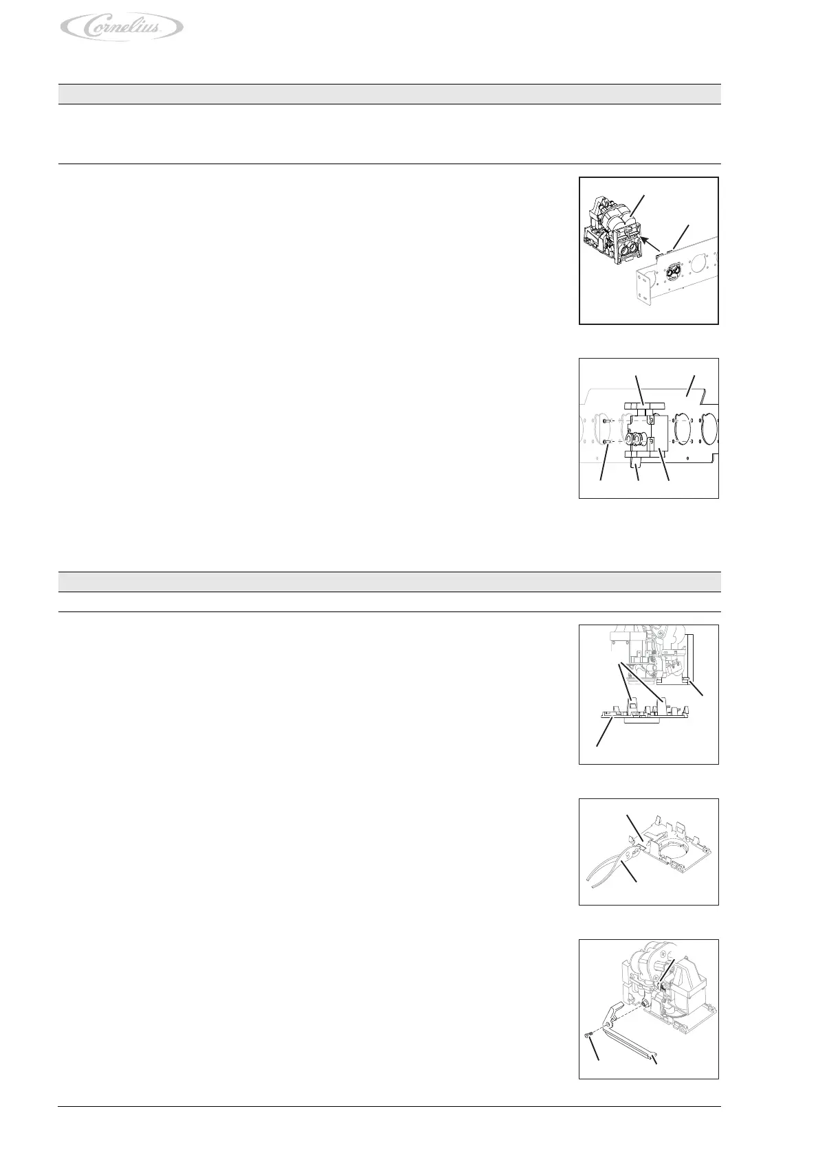
4.2 Removing the dispensing valve
4.3 Installing the soda lever
Prerequisites References
The base unit has been shut down. See base unit documentation
The front valve cover has been removed. see chapter 6.1
The rear valve cover has been removed. see chapter 6.2
1. Drain the dispensing valve.
2. Remove the dispensing valve (Fig. 7/1) from the block mount (Fig. 7/2) by pushing the hook
(Fig. 8/4) to the side, pushing the locking mechanism (Fig. 8/1) upwards and pulling the dis-
pensing valve (Fig. 7/1) from the block mount (Fig. 7/2).
Fig. 7
3. Remove the fastening bolts (Fig. 8/5) from the block mount (Fig. 8/3).
4. Remove the block mount (Fig. 8/3) from the dispensing valve support (Fig. 8/2).
Fig. 8
Prerequisites References
The dispensing valve has been removed. see chapter 4.2
1. Remove the base plate (Fig. 9/3) of the dispensing valve by pushing the two side tabs (Fig. 9/
1) apart and carefully pulling the base plate (Fig. 9/3) forwards and downwards from the valve
body (Fig. 9/2).
Fig. 9
2. Using pliers (Fig. 10/2), carefully break the bar out of the base plate (Fig. 10/1).
3. Fasten the base plate (Fig. 9/3) of the dispensing valve by inserting the base plate (Fig. 9/3)
with the rear tabs into the valve body (Fig. 9/2) and carefully pushing the base plate (Fig. 9/3)
upwards until the side tabs (Fig. 9/1) engage.
Fig. 10
4. Position the soda lever (Fig. 11/2) on the dispensing valve.
Make sure that the soda lever (Fig. 11/2) locks into place on the banjo shaft (Fig. 11/1).
5. Attach the soda lever (Fig. 11/2) using the fastening bolt (Fig. 11/3).
Do not overtighten the fastening bolt (Fig. 11/3).
Finishing tasks
1. Mount the dispensing valve, see chapter 4.1.
Fig. 11