Repairs
Cornelius Deutschland GmbH
Document no. TD2005100
Version 15/03/2019, Index 0
Installation and service manual Dispensing valve
SFV1
15
6Repairs
DANGER!
Risk of personal injury and equipment damage due to non-compliance with safety information!
If you fail to observe the safety information, you risk creating operating conditions at the dispensing valve which
may cause personal injury or damage to equipment.
• Please always strictly observe all safety measures and information/instructions, see chapter 1.
NOTICE!
All installation, maintenance and repair work on the dispensing valve must be carried out by an expert only.
WARNING!
Risk of personal injury and equipment damage due to operation by non-qualified staff!
It is dangerous for non-qualified staff to operate the unit!
• Service operations on the dispensing valve may only be carried out by trained and certified experts who
have been trained in undertaking service operations on the dispensing valve.
• All wiring and plumbing must be carried out in compliance with national and local laws, regulations and
guidelines. Non-compliance with these laws, regulations and guidelines may result in death, serious injury
or equipment damage.
6.1 Replacing the front valve cover
NOTICE!
The replacement procedure for the front valve cover is exactly the same on the dispensing valves SFV1.
Replacement is described here analogously using an example.
Prerequisites References
The base unit has been shut down. See base unit documentation
Spare parts ID/reference Qty/amount Comment
SFV1 portion control: Valve cover front 620050576 1
SFV1 push button: Valve cover front 620050576 1
SFV1 dosing lever: Valve cover front 620050574 1
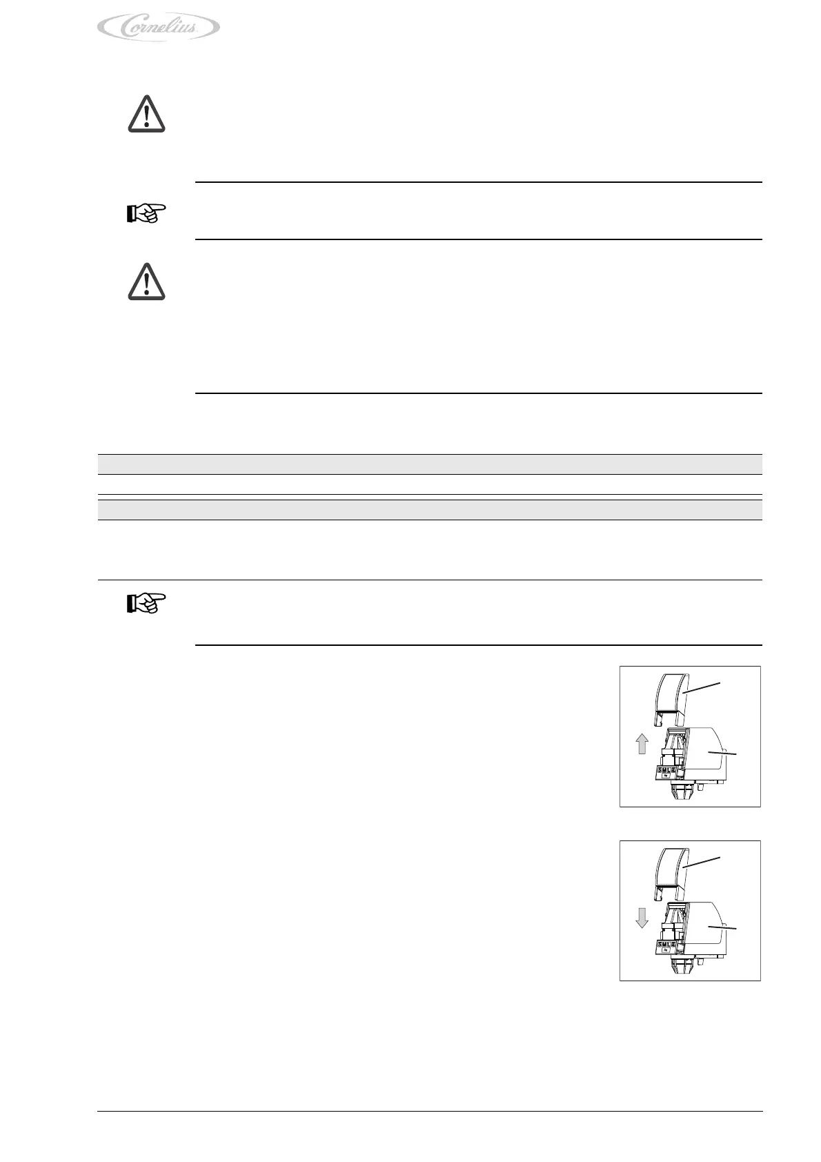
1. Push the front valve cover (Fig. 18/1) upwards and lift the front valve cover (Fig. 18/1) off the
dispensing valve (Fig. 18/2).
Fig. 18
1
2
2. Position the new front valve cover (Fig. 19/1) on the dispensing valve (Fig. 19/2).
3. Push the front valve cover (Fig. 19/1) downwards onto the dispensing valve (Fig. 19/2).
Fig. 19
1
2