Viper Low overrun Service Manual
© 2016, Cornelius Inc - 5 - Publication Number: 621360241LOEWSE
SYSTEM OVERVIEW
INTRODUCTION
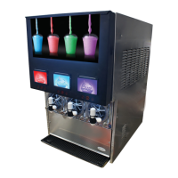
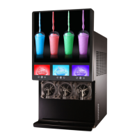
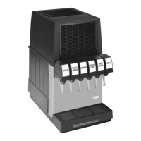
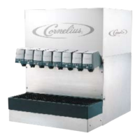
The Viper unit consists of the following systems and hardware:
Multiple freeze barrels, each containing an internal scraper bar driven by an AC motor.
A refrigeration system and an intelligent, hot gas defrost system.
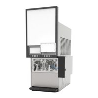
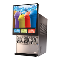
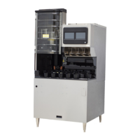
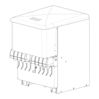
The components are enclosed in a powder-coated steel frame to prevent corrosion. It is covered with ventilated
cladding panels and a lighted merchandiser. The cladding is easily removable to facilitate installation, service and
maintenance.
Each barrel has a transparent faceplate, with an integral relief valve and a removable, self-closing dispensing valve
mounted on the front. A removable drip tray, with cup rest is located directly below the dispensing valves.
A programmable control system with a control panel that controls operational and diagnostic functions and settings
is located behind the merchandiser.
THEORY OF OPERATION
The refrigeration system schematic is shown in Figure 2. It shows the basic configuration for the Viper refrigeration
system.
The wiring diagram of the 3-Barrel Viper unit is shown in Figure 3. This diagram shows the details of the electrical
connections in the unit.