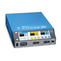
Power Supply/RF Board
4-28 Force FX Electrosurgical Generator C Service Manual
The averaged signal (now called VPK+) is input to the feedback microcontroller on the
Control board and added to the ECON value at the selected power setting. The sum of
these signals, with the proper gain factors, varies linearly with load impedance at the
patient site.
This sum is input into a pulse width modulator that sends its output (WAK\) to a NAND
gate. Thus, the T_ON\ signal is inhibited for up to four consecutive cycles. Without the
leakage control, the pulse repetition period is 17 µs. With the leakage control fully
activated, the total pulse train repeats every 84 µs with a maximum dead time of 60% or
51 µs.
REM Circuit
Components U17 along with R95, R96, R97, and C79 form a precision oscillator. R96 is
adjusted for the frequency that will produce maximum voltage amplitude (80 ± 10 kHz)
at the REM connector (J17). R98 is a temperature compensating thermocouple that
cancels temperature drift from the components forming the oscillator.
The REM transformer (T10) provides isolated reflected impedance sensing for tissue
impedance across the REM patient return electrode terminals (connected to J17, pins 1
and 2). In addition to tuning the REM circuit, capacitors C155, C156, C169, and C170
provide a return path for high frequency RF signals through C157 to the RF output
transformer. The REM transformer (T10) and capacitors C155, C156, C169, and C170
form a resonant circuit with a nominal operating frequency of 80 kHz.
Pin 1 of T10 clocks the active synchronous rectifier formed by CMOS switch U28A. This
device is closed during the positive period of the REM_AC signal and open during the
negative period. When the switch is closed, C122 is charged to the peak positive value of
REM_AC. Then, U31B amplifies, filters and buffers the charge on C122 to produce the
R_SEN signal. The microcontrollers monitor the R_SEN signal (which is a DC voltage
proportional to impedance) to determine the patient return electrode status.
IsoBloc Circuit
The IsoBloc circuit provides a means of detecting a switch closure in an output accessory
while maintaining electrical isolation between the generator output and ground
referenced circuitry.
The IsoBloc circuit consists of an isolated DC power supply, a comparator to detect switch
closure, and an optoisolator link from the output connected circuitry to the ground
referenced low voltage circuitry. Each handswitching output of the generator is
associated with its own IsoBloc power source and isolated signal paths.
Oscillator
The oscillator circuit consists of a chain of 74HC14 inverters. The output of the oscillator
yields a 67.5 kHz square wave that is applied to the input of three 4081 buffers (U29).