Power Supply/RF Board
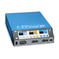
4-24 Force FX Electrosurgical Generator C Service Manual
The low voltage power supply specifications are as follows:
*Total output power cannot exceed 40 W.
RF Output Stage
The RF stage consists of a single MOSFET power switch with associated gate drive
circuitry, an RF power transformer, tuning capacitors, an RF output L-C-C filter, output
directing relays, and topology selecting relays. Also included in this section are the RF
voltage and current sense circuits and a switched damping network for certain
operational modes.
The MOSFET gets its gating signal from the T_ON ASIC on the Control board. The T_ON
ASIC also provides the gating signal for the switched damping network.
When the topology selecting relays (K2 and K14) are unenergized, the RF stage is in the
Fulgurate and Spray coag modes; when both are energized, the RF stage is in the cut and
bipolar modes. For the Desiccate coag mode, K2 is unenergized and K14 is energized.
Primary Sense Circuits
The primary voltage and current sense circuits provide feedback information to the
feedback microcontroller in the bipolar and cut modes.
For voltage sensing, the two 10 k : resistors (R148 and R149) in series with the primary
of T13 work with the 100 : resistor across the secondary to divide the output voltage
down.
Depending on the front panel power setting, one of the four relays (K3 to K6) is switched
in to give optimum scaling. The four AD827 high speed op-amps, along with the
associated resistors, capacitors, and diodes, form a precision full wave rectifier circuit.
U11B is a high input impedance follower to prevent the rectifier circuit from loading
down the resistive divider. U11A is a follower that adds phase delay, which improves
balance in the rectified waveform between positive and negative half cycles of the input
signal.
Output Voltage Output Current Output Power*
+5 Vdc 4000 mA 20.0 W
-12 Vdc 400 mA 4.8 W
+12 Vdc 2000 mA 24.0 W
Warning
High frequency, high voltage signals that can cause severe burns are present in the RF output
stage and in the associated mounting and heat sink hardware described in this manual. Take
appropriate precautions when testing and troubleshooting this area of the generator.