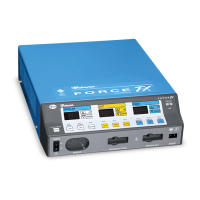
Display Board
4-14 Force FX Electrosurgical Generator C Service Manual
Display Board
Refer to Chapter 9, Service Parts, for components and the Schematics Supplement for
board drawings and schematics.
The Display board is located in the front panel assembly. It contains RF indicator lamps,
seven-segment LED power setting displays, REM alarm LEDs, and a CEM indicator LED.
The Display board switch circuitry includes the LED and lamp driver circuitry, power
selection switches, mode selection switches, the REM switch circuit, and the CEM switch
circuit.
RF Indicator Lamps
The RF indicator lamps illuminate during RF activation to visually indicate the presence of
RF power. Each of the three indicator bars (Bipolar, Cut, and Coag) on the front panel is
illuminated by four incandescent bulbs (LP1–LP12).
•LP1–LP4 illuminate the blue Bipolar bar, indicating bipolar activation.
•LP5–LP8 illuminate the yellow Cut bar, indicating cut activation.
•LP9–LP12 illuminate the blue Coag bar, indicating coag activation.
The RF indicator lamps are controlled by the BIP_LMP, CUT_LMP, and COAG_LMP signals.
These signals originate from port A of the main microcontroller programmable peripheral
(U3) on the Control board.
Buffers in U1 turn the RF indicator lamps on and off. Resistors R1–R12 set the amount of
current flowing through the lamps when they are turned on. The value of these resistors
varies for each indicator bar, depending on the color of the bar, to make the different
colors of the bars illuminate with equal intensities.
REM Indicators
The REM indicator consists of two bicolor LED arrays incorporating one red and four
green LEDs per array. The LEDs are controlled by the REM_RED and REM_GREEN signals
originating from port A of the main microcontroller programmable peripheral (U3) on the
Control board. The signals are buffered on the Display board by driver U1. Both the red
and green LEDs are current limited by 100 : resistors (R13, R14, R15, and R16).
LED and Seven-Segment Display Drivers
This circuit contains three display drivers for the LEDs and the seven-segment displays.
The LEDs indicate modes of operation, and the REM condition. The seven-segment
displays indicate bipolar, cut, and coag power settings.