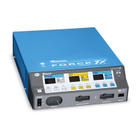
Power Supply/RF Board
Principles of Operation
Force FX Electrosurgical Generator C Service Manual 4-25
The actual rectification is done with U8A and U8B. The rectified waveform is converted to
DC by the R-C filter after the last op-amp, with full scale being 5 Vdc.
The current sense circuit, which uses current transformers T6 and T8, works the same as
the voltage sense circuit. T6 senses bipolar current and T8 senses monopolar current.
Relay K7 selects the appropriate current. Note that the current scaling relays (K8 to K11)
switch at different power settings than the voltage scaling relays.
Redundant Sense Circuits
Redundant voltage and current sense circuits provide dosage error monitoring.
T16 monitors the current through the output capacitors (C150, C152, and C158). This
current is proportional to the output voltage of the generator. A full bridge rectifier is
formed by CR25–CR28. The rectifier output is filtered by R118 and C96. Op-amp U18
buffers the DC signal. R119 and C97 provide additional filtering.
T17 and the associated circuitry operate the same as the redundant voltage sense circuit.
The output is a signal proportional to the output current of the generator.
Cut Modes
In the cut modes, K2 is set so that diode CR2 is in parallel with the MOSFET body drain
diode, C34 and C41 are across the MOSFET, and the transformer primary consists of
windings 1-2 and 3-4 in series. K14 is closed so the series capacitor bank (C150–C152,
C158, and C159) is across the output.
In the Low and Pure cut modes, the T_ON\ signal is a continuous pulse train with a pulse
width of 846 ns and a frequency of 390 kHz. In this case, essentially two resonant circuits
operate in tandem.
The output L-C filter is tuned just slightly higher than the RF switching frequency,
achieving a high degree of filtering. The output is very sinusoidal over the full range of
load impedances.
Capacitors C34 and C41 are tuned with the RF transformer primary so that the flyback
voltage appearing across the MOSFET at turn off is a half sine pulse and returns to zero
volts before the next cycle begins. The T_ON\ pulse width is chosen to support this
tuning. This zero voltage switching improves the efficiency of the RF stage and is effective
over a wide range of load impedances.
The circuit topology of the Blend cut mode is the same as the Pure cut mode. In Blend mode,
however, the T_ON\ signal is an interrupted pulse train with a 50% duty cycle and a pulse
train repetition rate of 27 kHz.
For a given power setting, Blend gives a higher peak current, providing better hemostasis
than Pure or Low. To minimize ringing at the beginning of the off period of the Blend
waveform envelope, the damping resistor is switched on just before switching ends and stays
on for part of the off period.