4 • 485 Alarm Panel 026-1701 Rev 0 01-05-98
cessible without removal of any boards inside the enclo-
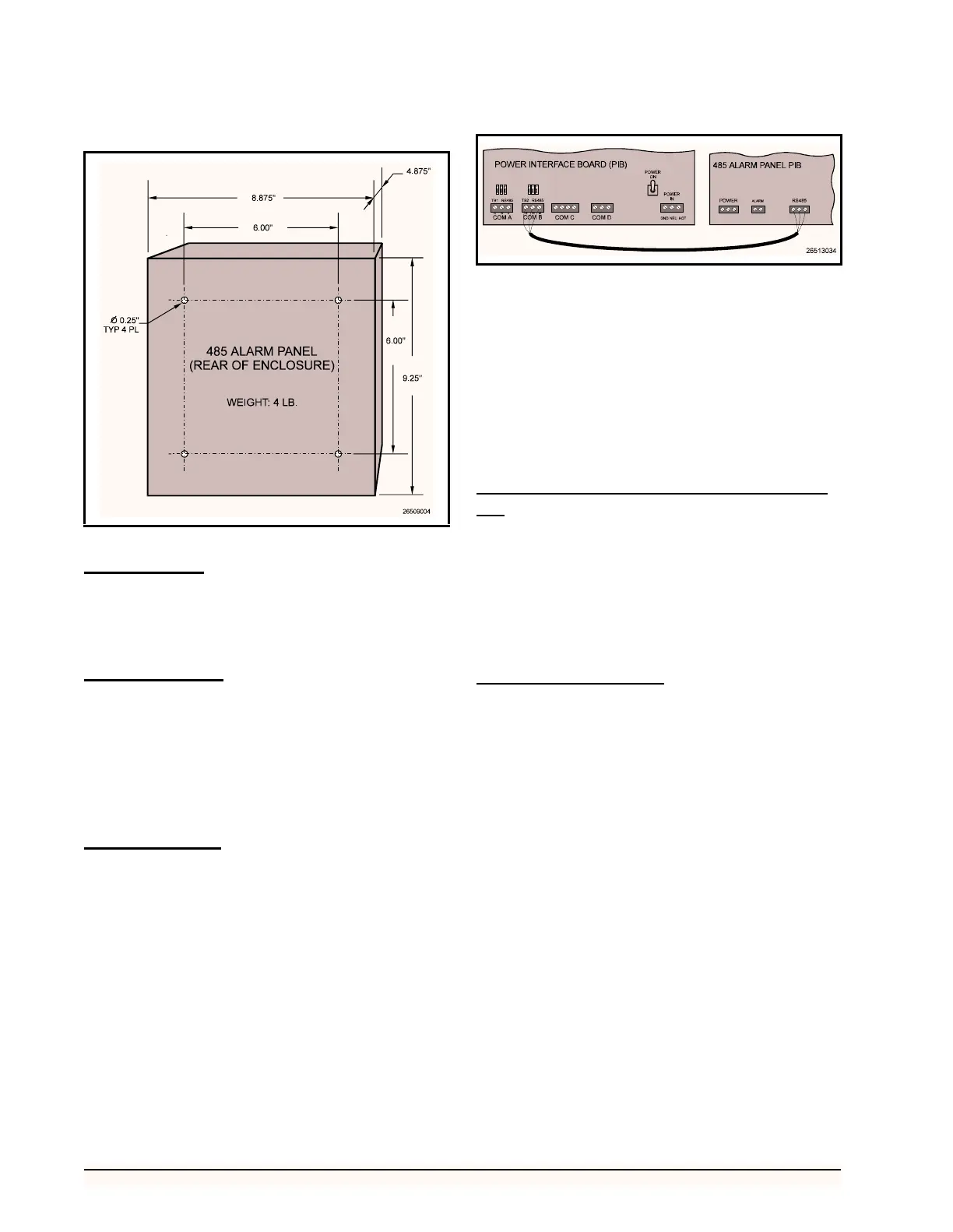
sure. Figure 2 shows the enclosure dimensions and weight.
Power Wiring
Connect the 485 Alarm Panel to the power supply at the
three terminals labelled POWER IN. Connect the ground to
terminal G, the neutral to terminal N, and the hot wire to
terminal H.
Power Jumpers
If 120VAC power is being used, set jumpers JU1 and
JU2 to the DOWN position as shown in Figure 4 on page
6. If 208VAC power is being used, set jumpers JU1 and
JU2 in the UP position.
If you ordered the 24VAC alarm panel, jumpers JU1
and JU2 will be hard-wired to the correct position. No ad-
justment will be necessary.
Network Wiring
The 485 Alarm Panel connects to one or more RE-
FLECS units via the RS485 Host Network (COM B). Us-
ing a Belden #8641 or equivalent cable, connect the three
terminals labelled RS485 Network on the 485 Alarm Panel
to the three COM B terminals on the REFLECS Power In-
terface Board (PIB), as shown in Figure 3.
1. Using the RED wire, connect the positive ter-
minal (+) on the alarm panel to the positive
(+) terminal on COM B.
2. Using the BLACK wire, connect the negative
terminal (-) on the alarm panel to the negative
(-) terminal on COM B.
3. Connect the cable shield wire from the com-
mon terminal (0V) on the alarm panel to the
common (0V) terminal on COM B.
Network Terminating Resistance Jump-
ers
If the 485 Alarm Panel is connected to only one RE-
FLECS via its RS485 Network terminals, place jumpers
JU3, JU4, and JU5 in the UP position.
Otherwise, if the panel is connected in between two
REFLECS units (i.e. NOT at the end of the RS485 Host
Network), place jumpers JU3, JU4, and JU5 in the DOWN
position.
Device ID Numbering
The 485 Alarm Panel must be given a COM B network
device number. Refer to your REFLECS Installation and
Operation Manual for more details on COM B device num-
bering.
Rockers 1 through 5 on switch SW2 on the 485 Alarm
Panel board are used to set the 485 Alarm Panel’s device
number. To set the device ID, set the switches as shown in
Table 1.
Figure 2 - 485 Alarm Panel Mounting Dimensions
Figure 3 - COM B Wiring - REFLECS to 485 Alarm Panel