38 • Standard Pressure Transducers 026-1701 Rev 0 01-05-98
Each pressure transducer is supplied with 20 feet of ca-
ble for connection to a 16AI input board. Table 11 shows
the corresponding output voltage for each transducer.
Installation
1. Ensure that the copper gasket supplied with
the unit is properly seated at the base of the
flare fitting.
2. Screw the transducer onto the access valve.
Do not exceed a maximum torque of 11 ft-lb.
Do not apply torque to the case.Use a wrench
on the wrench flats.
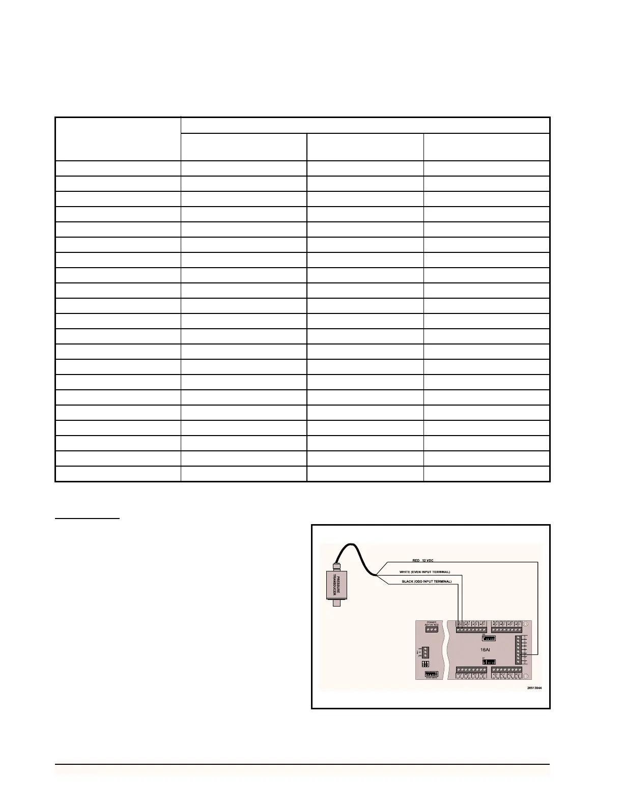
3. Connect the transducer to a 16AI board as
shown in Figure 27.
Software Requirements
All BEC, BCU, and RMCC software (except version
2.10 and above) are pre-configured to accept standard pres-
sure transducers; therefore, no software setup is required
for SPTs.
Output Voltage (VDC)
Pressure in PSIG
0-100 PSIG Standard
Transducer
0-200 PSIG Standard
Transducer
0-500 PSIG Standard
Transducer
1.00 0 0 0
1.25 5 10 25
1.50 10 20 50
1.75 15 30 75
2.00 20 40 100
2.25 25 50 125
2.50 30 60 150
2.75 35 70 175
3.00 40 80 200
3.25 45 90 225
3.50 50 100 250
3.75 55 110 275
4.00 60 120 300
4.25 65 130 325
4.50 70 140 350
4.75 75 150 375
5.00 80 160 400
5.25 85 170 425
5.50 90 180 450
5.75 95 190 475
6.00 100 200 500
Table 11-Voltage-Pressure Table for 100, 200, 500 PSIG Standard Pressure Transducers
Figure 27-Standard Pressure Transducer Wiring Diagram