Peripherals Manual Indoor Relative Humidity Sensor (P/N 203-5750) • 23
Indoor Relative Humidity Sensor (P/N 203-5750)
Overview
The indoor relative humidity sensor uses a capacitor-
based humidity sensor for measurement of relative humid-
ity. The indoor humidity sensor (P/N 203-5750) comes
with an enclosure designed to be mounted on a wall.
The sensing element for indoor humidity sensor is a
General Eastern bulk resistance type sensor. Table 4 lists
the sensor’s specifications:
Installation
Mounting the Indoor RH Sensor
The indoor relative humidity sensor should be mounted
in a central location within the zone to be measured, away
from doors, windows, vents, heaters, and outside walls that
could affect temperature readings. The sensor should be be-
tween four and six feet from the floor.
Mount the sensor as follows:
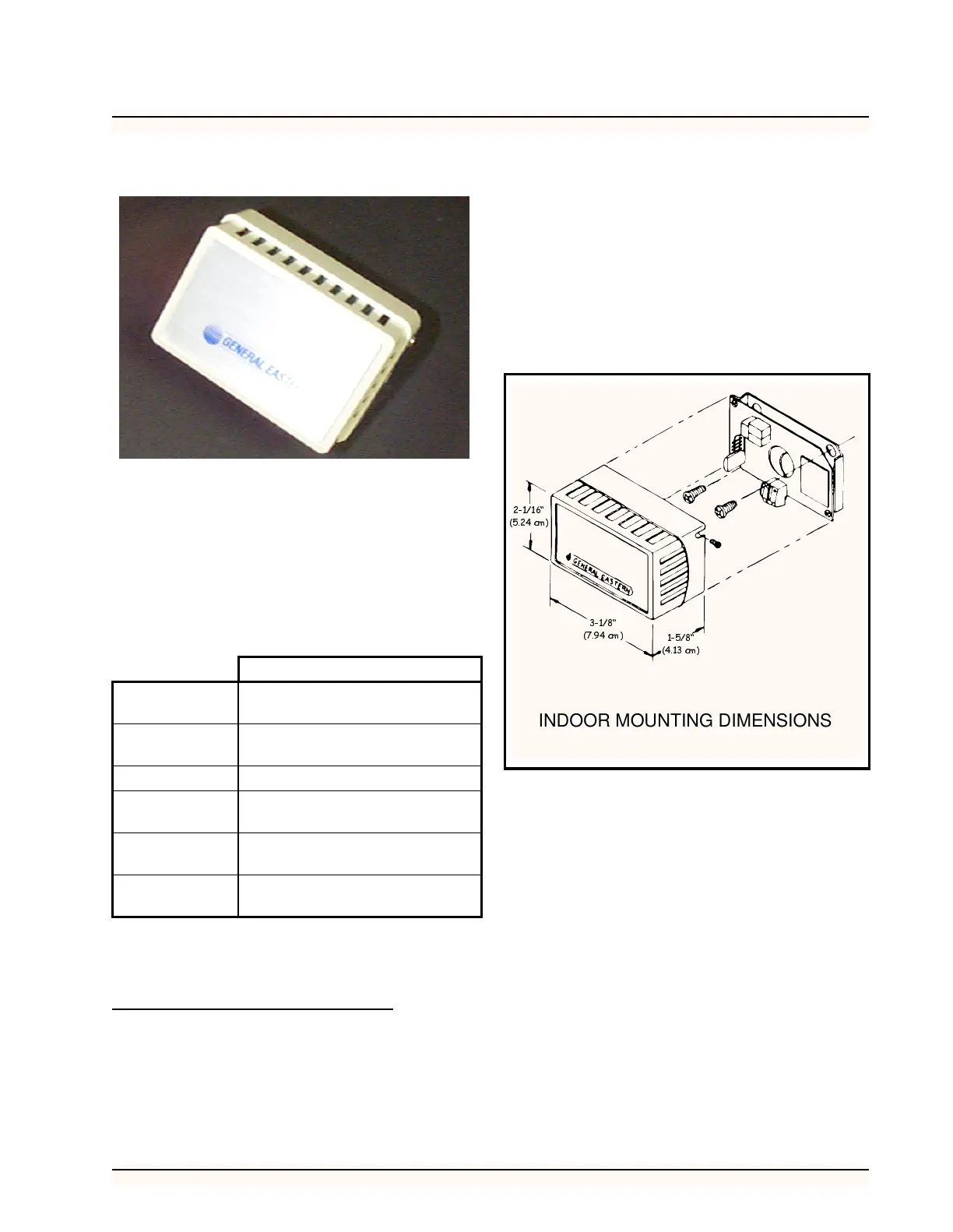
1. Remove the two screws from the sides of the
enclosure, and remove the cover.
2. Mount the sensor to the wall using the two
mounting holes near the flattened corners of
the mounting plate (as shown in Figure 19).
3. Replace the cover and the cover mounting
screws.
Wiring
Wire the relative humidity sensor to an input board as
shown in Figure 20.
1. Wire the terminal labelled “P” to one of the
12V supply terminals on the input board
(POWER).
2. Wire the terminal labelled “GND” to the odd-
numbered terminal of an input board point
(GND).
3. Wire the terminal labelled “OUT” to the
even-numbered terminal of an input board
point (SIG).
4. Jumper the terminal labelled “N” to the
“GND” terminal.
Specifications
Operating
Range
10% to 99% RH (noncondensing)
-40° to 170° F (-40 to 76° C)
Storage Tem-
perature
-85° to 158° F
(-65° to 70° C)
Hysteresis
Less than 1% RH
Supply Volt-
age
9.5 to 36 VDC
Signal Out-
puts
0 to 5 volts (0 to 100% RH linear)
Accuracy
Range
±3%
Table 4 - RH Sensor Specifications
Figure 19 - Indoor RH Mounting Dimensions
26509025
´
FP
´
FP
´
FP
INDOOR MOUNTING DIMENSIONS