Peripherals Manual Refrigerant Liquid Level Sensor (P/N 207-0100) • 43
Refrigerant Liquid Level Sensor (P/N 207-0100)
Overview
The LA100SD-U Refrigerant Liquid Level Sensor is
designed to be used as a tank-mounted sensor. This sensor
can be connected to a 16AI board to monitor tank levels.
Installation
This installation procedure does not require the pump-
down of the tank or refrigeration evacuation.
1. Remove existing float gauge LL-1 (two 6/32
screws. Do not loosen or remove the four cor-
ner screws.
2. Replace LL-1 with the LA100SD-U electron-
ic sensor using the two 6/32 x 1/2” screws
provided. The spacers and gasket supplied
may be required if sensor readings are not
within a reasonable range of the mechanical
float gauge LL1.
If you need to use the spacers and gaskets, do
not overtighten screws. If spacers are not re-
quired, do not discard. Place the spacers in
between the screw heads and the outside of
the mounting bracket.
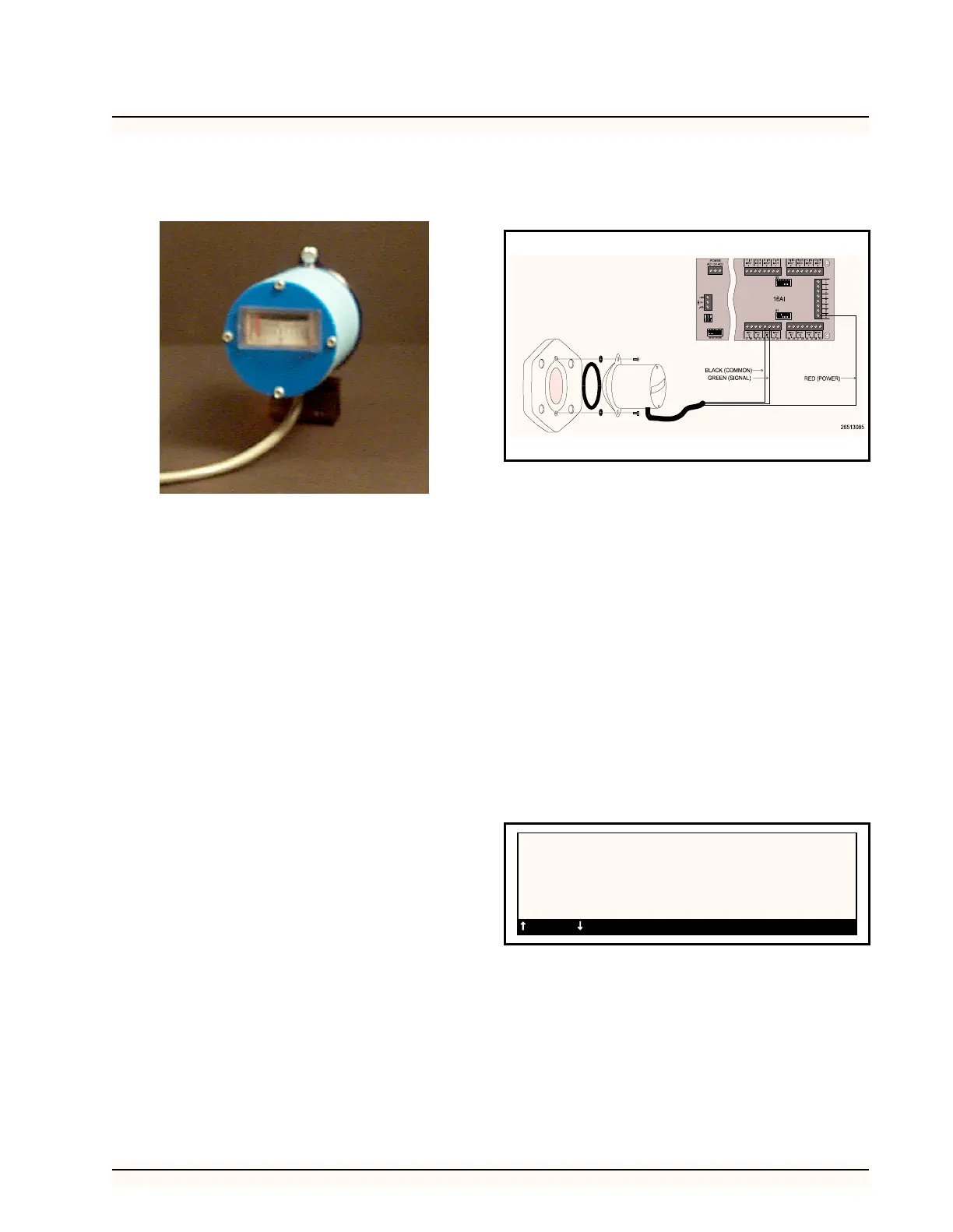
3. Wire the liquid level sensor as shown in Fig-
ure 34 with the Black wire (common) con-
nected to a odd terminal on an available point
of a 16AI board, the Green wire (signal) con-
nected to an even terminal on the same point,
and the Red wire (power) connected to a 12 V
terminal on the 16AI.
4. If extending the cable is required, use a
shielded cable with three conductors such as
Belden #8771 or Belden #9363. Ground the
shield to the same odd 16AI terminal as the
“common” connection. Do not connect the
shield at the end of the cable near the sensor.
5. Set the corresponding dip switch in the down
position.
Software Setup
1. After you assign the liquid level sensor to a
board and point number, you will need to set
the type of sensor you are using.
2. Select Setup from the sensor control menu
and select the sensor you wish to setup. In the
type field, scroll through the types until the
RMCC displays LiqLvl in the type field.
Figure 34-Wiring Diagram for Refrigerant Liquid Level Sensor
SENSOR SETUP 12:00
#:01 Status:OFF Name:LIQUID LEVEL
Type: Liqlvl
Logging Interval (HH:MM:SS): 00:03:00
=PREV =NEXT ->=SET-DATA 0=MENU