28 • Refrigerant Transducer (P/N 809-1550) 026-1701 Rev 0 01-05-98
tion. However, it is likely that multiple RTs will be in-
stalled and, therefore, an additional power supply must be
provided. Because RTs draw high current during power up,
a power supply with delayed foldback current limiting is
required. Delayed foldback current limiting prevents cur-
rent limiting long enough for the power supply to reach 12
volts. If more than one transducer per 16AI board is to be
installed, connect the RTs to CPC Power Supply (P/N 258-
1000).
Location
The RT is designed to monitor an area of 1000 cubic
feet, and should be mounted to allow the leak sensor to de-
tect a refrigerant leak quickly. Consideration should be giv-
en to air flow patterns, proximity to doorways, and
interference that could limit the ability of the transducer to
sense a refrigeration leak. Since refrigerant is heavier than
air, the lower the location of the RT, the more quickly the
RT will detect a refrigerant leak.
Non-Refrigerant Gas Detection
The refrigerant transducer uses a metal oxide coated re-
sistor for detecting refrigerants. Although highly sensitive
to CFCs and HCFCs, the sensor will also detect other gases
present in the sensing area. By programming alarm and no-
tice delay set points within the CPC controller, detection of
these gases can be filtered to ensure only CFC or HCFC de-
tection causes alarm or notice conditions. Some of the gas-
es that will be detected by the RT are listed below:
• Methyl Chloride
• Methylene Chloride
• Chloroform
• Carbon Tetrachloride
• Ethyl Chloride
• Ethylene Chloride
• Trichlorothane
• Tetrachloroethyelane
• Chlorobenzene
• Ethanol
• Octane
• Hexane
• Carbon Monoxide
•Isobutane
• Carbon Dioxide
Mounting
The RT is 3.2 inches wide, 2.1 inches high, and 1.6
inches deep.
1. Loosen the cover set screw on both sides of
the protective cover, and remove the cover.
2. Loosen the two board mount screws, and re-
move the board from the mount plate.
3. Secure the mount plate using four screws.
4. Remount the board using the two mount
screws.
5. After wiring, replace the protective cover and
set screws.
System Connections
A total of 16 refrigeration transducers may be installed
on one 16AI board. This limitation is due to the total num-
ber of input terminals on the board. In addition, no more
than 16 RTs may be connected to one external power sup-
ply. Regardless of the number of sensors connected to the
input terminal of the 16AI, only one RT may be connected
to the power output connection of the board. The following
layouts should be used when installing single or multiple
RTs.
The RT and the 16AI board do not need to be located
close to each other. Table 7 lists the maximum cable
lengths and required cables for RT connection to the 16AI
board.
Single Refrigerant Transducer Layout
Connect the refrigerant transducer to the 16AI input
board as shown in Figure?.
1. Attach the black wire to the -V terminal of the
RT and attach the green wire to the 0V termi-
nal of the RT.
2. Tie the back and green wires together at an
odd terminal of the 16AI input connection.
3. Attach the white wire to the OUT terminal of
the RT and an even terminal of the 16AI
board input connection.
4. Attach the red wire to the +V terminal of the
RT and a 12V terminal on the 16AI power
output connection.
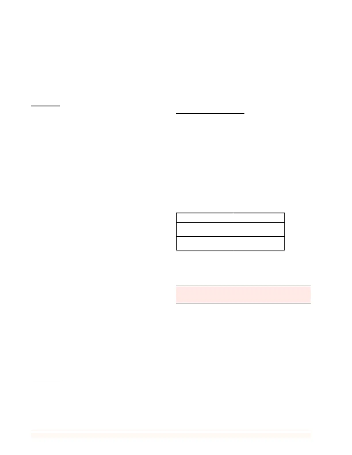
Max Cable Length Cable Type
700 Belden #8729
(22AWG or equiv.)
1800 Belden #9418
(18AWG or equiv.)
Table 7 - RT Connection Cable Lengths
Do not jumper the -V and 0V terminals of the refrig-
erant transducer.