10 • RS232 Bus Amplifier (P/N 812-1800) 026-1701 Rev 0 01-05-98
System Connections
The RS232 Bus Amplifier can be connected to the ex-
isting refrigeration system in a variety of ways depending
upon the relative proximity of the compressor racks, other
CPC controllers, and the local computer terminal to each
other.
Table 2 provides a brief description of the RS232 Bus
Amplifier ports, connecting components, and the cable
type required for system connection:
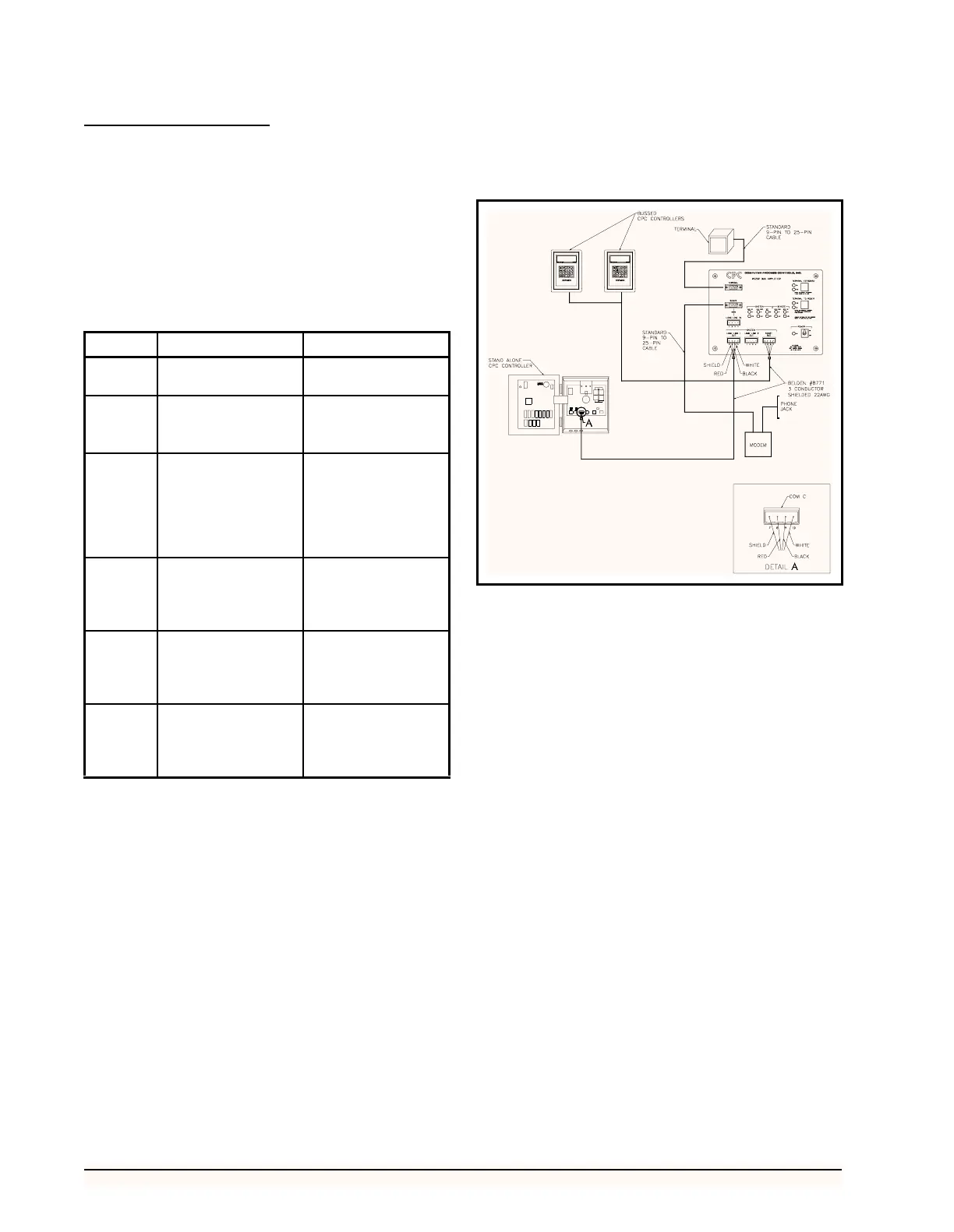
Single-Amplifier Layout
In general, the RS232 Bus Amplifier will be installed in
close proximity to the CPC controllers, modem, and local
computer terminal. Figure 6 shows this layout.
If the CPC controllers, modem, and local computer ter-
minal are located adjacent to one another, connect the
RS232 Bus Amplifier to the system as follows:
1. Connect the modem to the REMOTE MO-
DEM PORT using a standard 9-pin to 25-pin
cable.
2. Connect the computer terminal to the TER-
MINAL PORT using a standard 9-pin to 25-
pin cable.
3. Connect the bussed CPC controllers to the
SYSTEM SHORT BUS PORT using a
Belden #8771 (three conductor shielded
22AWG) cable.
4. Connect any stand-alone CPC controller
(such as a BEC) to the SYSTEM LONG
LINE 1 OUT PORT using a Belden #8771
(three conductor shielded 22AWG) cable.
Two-Amplifier Layout
In some cases, location of the modem and local termi-
nal will not allow location of the bus amplifier to both the
modem and local terminal and the CPC controllers. Since
data loss is possible when multiple CPC controllers trans-
mit data over long cable lengths, it may be necessary to
connect the CPC controllers to a remote amplifier adjacent
Port Description Cable Type
Terminal Local Computer Ter-
minal
Standard 9-25 pin
Modem
(Remote)
Modem
Satellite
Standard 9-25 pin
Determined by satel-
lite system
Long
Line In
(Remote)
Laptop Computer
Remote Bus Amplifier
to Main Bus Amplifier
DB9 REFLECS Lap-
top Cable (P/N 535-
1190)
Belden #8771 (Three
Conductor Shielded
22AWG)
Long
Line 1
Out
Stand-alone CPC Con-
troller
Main Bus Amplifier to
Remote Bus Amplifier
Belden #8771 (Three
Conductor Shielded
22AWG)
Long
Line 2
Out
Stand-alone CPC Con-
troller
Main Bus Amplifier to
Remote Bus Amplifier
Belden #8771 (Three
Conductor Shielded
22AWG)
Short Bus
(System)
Multiple Bussed CPC
controllers
Belden #8771 (Three
Conductor Shielded
22AWG)
Table 2 - RS232 Bus Amplifier Port and Cable Description
Figure 6 - Typical Single-Amplifier Layout