16 • Checkit Refrigeration System Monitor (P/N 508-2000) 026-1701 Rev 0 01-05-98
Installation Procedure
1. Remove the sensor from the holding tube on
the vessel.
2. Solder the vessel directly into the refrigera-
tion line, or on a bypass line if the main line
is larger than 1-5/8".
3. After the vessel and refrigeration line have
cooled completely, apply Wakefield Thermal
Joint Compound #120-5 (CPC P/N 020-
7120) or equivalent on the sensor and re-in-
sert the sensor into the holding tube. (If nec-
essary, silicone sealer may be applied to the
end of the sensor after installation to help en-
sure the sensor remains in the holding tube.)
When installed, the sensor should fit com-
pletely within the holding tube.
4. Secure the sensor leads to the refrigeration
line with a standard cable tie located adjacent
to the sensor.
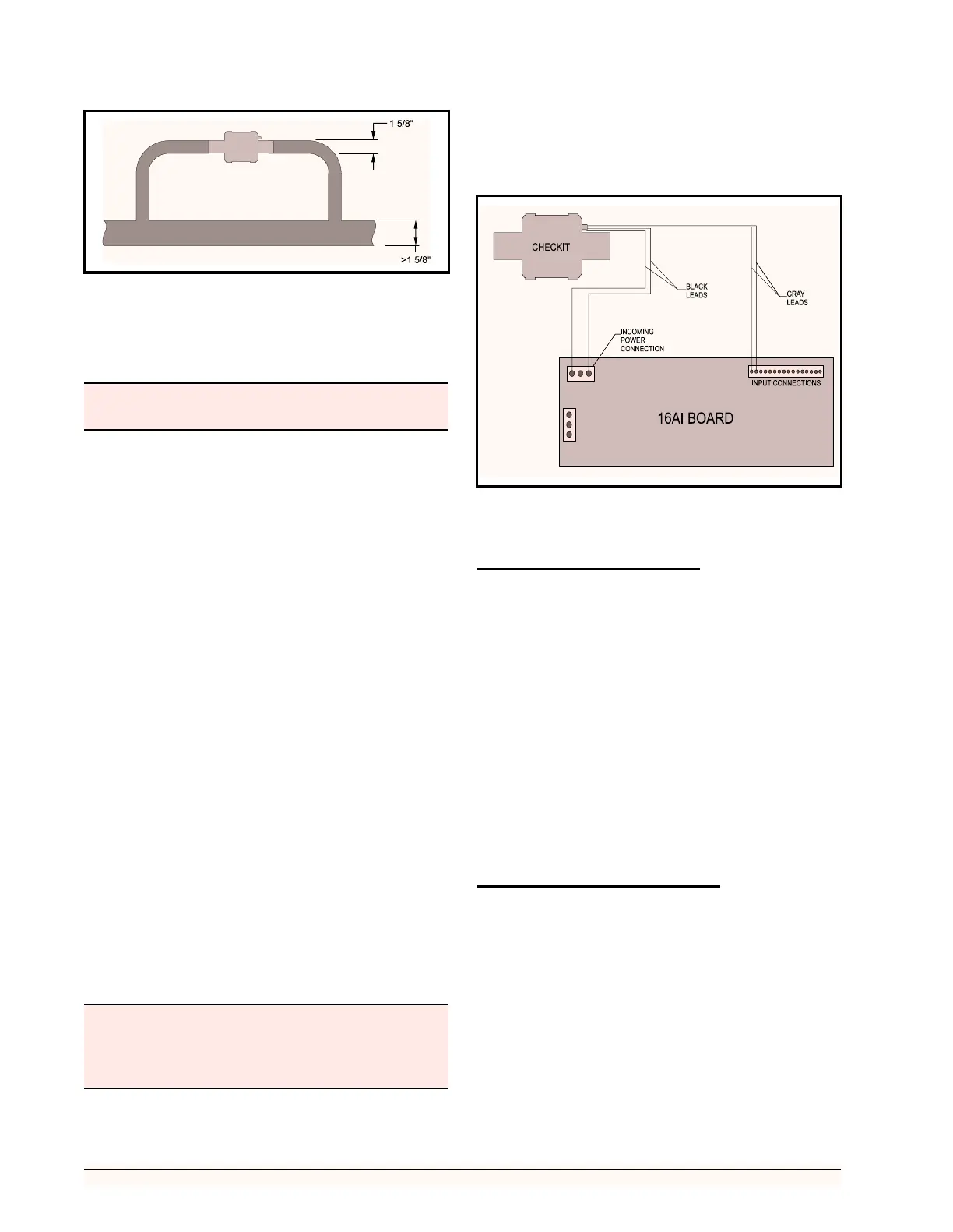
5. The Checkit sensor requires 24 VAC. Con-
nect the sensor leads as follows: (a)Connect
the two black leads to the 24 VAC output on
the 16AI board, as shown in Figure 14, or to
an alternate 24 Volt power source. (b)Con-
nect the two gray leads to an input on the
16AI board (the polarity of each of the leads
is not important). Set the corresponding in-
put’s dip switch to the UP position.
6. Checkit installation is complete.
If a damaged Checkit sensor needs to be replaced, fol-
low the instructions above, skipping Step 2, using a re-
placement sensor (CPC P/N 201-2010).
Set-up
Board and Point Settings
Before monitoring of the Checkit sensor by the RMCC
can begin, the location of the Checkit sensor must be iden-
tified. The following procedure should be used for location
identification:
1. Return to the Main Menu.
2. Select 7) Configuration from the Main Menu.
3. Select 1) Input Definition from the Configu-
ration Menu.
4. Page down the Input Definitions Pages to the
Checkit Page.
5. Input the 16AI board number and point num-
ber for the Checkit sensor.
6. Checkit sensor setup is complete.
Set Points and Time Delays
To configure the RMCC unit for Checkit monitoring,
the following procedure should be followed:
1. Log on the RMCC unit with the proper pass-
word.
2. Select 1) Pressure Control from the Main
Menu.
3. Select 3) Alarms from the Pressure Control
Menu.
4. Page down the Alarms Pages to the Checkit
Page.
Figure 13 - Installation of Checkit and Bypass for Lines Larger
than 1 5/8”
The Checkit sensor assembly may become hot during
the soldering process.
Power to the sensor should be shut-off and the sensor
allowed to cool completely if it becomes necessary to
remove the sensor from the holding tube for inspec-
tion or replacement.
Figure 14 - Checkit Typical Power Connections