22 • Light Level Sensor (P/N 206-0002) 026-1701 Rev 0 01-05-98
Software Setup
Input Board and Point Configuration
Set up the Light Level Sensor by assigning the board
and point address to the appropriate input. Refer to the RE-
FLECS Installation and Operation manual for more infor-
mation.
Sensor Setup
If the Light Level Sensor is being set up in Sensor Con-
trol, the Sensor type must be defined in the Sensor Setup
screen as a (L)inear sensor with a Gain of 175 and an Offset
of 0.
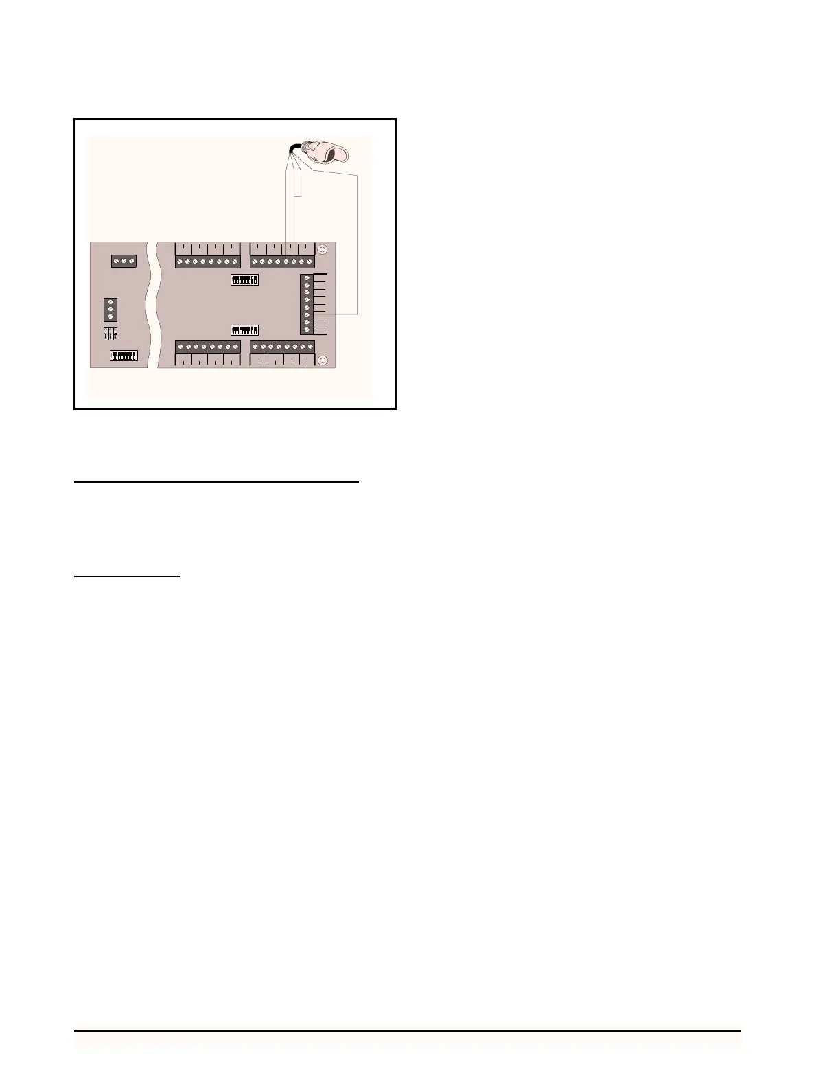
Figure 18-Light Level Sensor Wiring Diagram
23456781
ON
123
45
6
7
8 9 10 11 12 13 14 15 16
17 18 19 20 21 22 23 24 25 26 27 28 29 30 31 32
5
V
12
V
5
V
5
V
5
V
12
V
12
V
12
V
S1
S2
INPUT
1
INPUT
9
INPUT
2
INPUT
10
INPUT
3
INPUT
11
INPUT
4
INPUT
12
INPUT
5
INPUT
13
INPUT
6
INPUT
14
INPUT
7
INPUT
15
INPUT
8
INPUT
16
23456781
ON
S3 NETWOR K
POWER
AC1 0V AC2
+485
0V
-485
NET
16AI
2345678
1
ON
GREEN
RED
YELLOW
POWER (12 V)
26513081