Peripherals Manual RS232 Bus Amplifier (P/N 812-1800) • 11
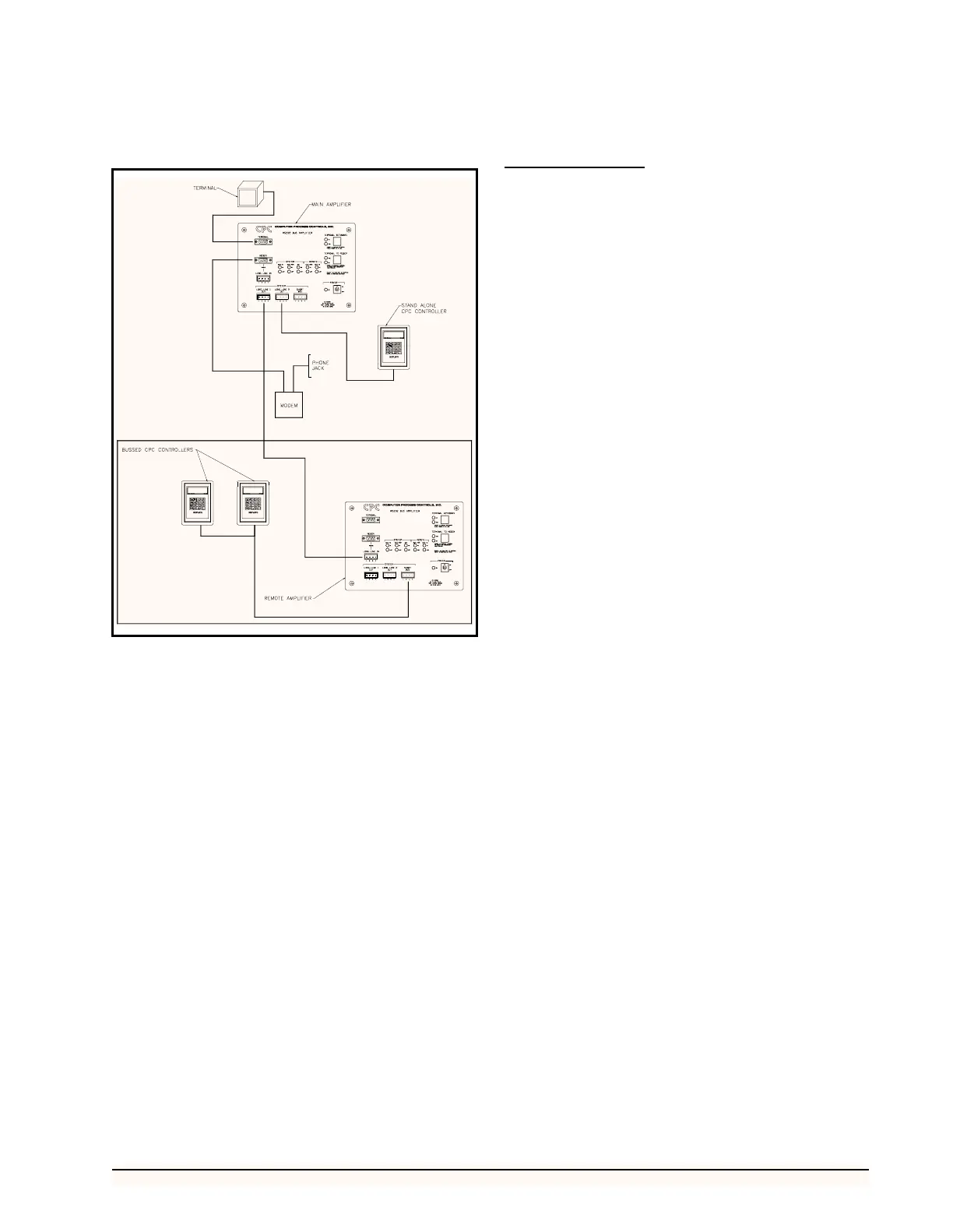
to the controllers, and then connect the remote amplifier to
a main amplifier connected to the modem and local termi-
nal. This two-amplifier installation is shown in Figure 7.
If the CPC controllers, modem, and local computer ter-
minal are not located adjacent to one another, install a re-
mote and main RS232 Bus Amplifier as follows:
1. Install the main RS232 Bus Amplifier adja-
cent to the modem and local computer termi-
nal as described in steps 1 and 2 above.
2. Install the remote RS232 Bus Amplifier adja-
cent to the bussed CPC controllers as de-
scribed in steps 3 and 4 above.
3. Connect the main bus amplifier to the remote
bus amplifier using a Belden #8771 (three
conductor shielded 22AWG) connected to
the SYSTEM LONG LINE 1 OUT PORT on
the main bus amplifier, and the REMOTE
LONG LINE IN PORT on the remote bus
amplifier.
System Description
Once connected to the system and a power source, the
RS232 bus amplifier will automatically perform the func-
tions necessary to improve system performance and com-
munication. However, there are a number of status lights
that will provide useful information concerning amplifier
operation and aid in troubleshooting if necessary. A brief
description of these indicators is provided below:
Indicator Lights
Power
A single green light to the left of the power switch illu-
minates when power is being supplied to the RS232 Bus
Amplifier.
System Data To Lights
The red SYSTEM DATA TO light, shown in Figure 4,
flashes when data are being transmitted to a CPC controller
or additional bus amplifier. If no data are being transmitted,
the green light remains illuminated. These lights are asso-
ciated with the RX output of each SYSTEM PORT.
System Data From Lights
The red SYSTEM DATA FROM light, shown in Figure
4, flashes when data are being received from a CPC con-
troller or additional Bus amplifier. If no data are being re-
ceived, the green light remains illuminated. These lights
are associated with the TX input of each SYSTEM PORT.
System Data Terminal Ready (DTR) Lights
The red SYSTEM DTR light, shown in Figure 4, illu-
minates when DTR is on. The green light illuminates when
the DTR OFF command is received from any CPC control-
ler or other bus amplifier. These lights are associated with
the DTR input of each SYSTEM PORT.
Remote Data From Lights
The red REMOTE DATA FROM light, shown in Fig-
ure 4, flashes when data are being received from the MO-
DEM PORT or the LONG LINE IN PORT. If no data are
being received from the modem, the green light remains il-
luminated. These lights are associated with the RX input of
the REMOTE LONG LINE IN PORT and REMOTE MO-
DEM PORT.
Remote Data To Lights
The red REMOTE DATA TO light, shown in Figure 8,
flashes when data are being transmitted to the REMOTE
MODEM PORT or REMOTE LONG LINE IN PORT. If
no data are being transmitted to the modem, the green light
remains illuminated. These lights are associated with the
TX output of the REMOTE LONG LINE IN PORT and
REMOTE MODEM PORT.
Figure 7 - Typical Two-Amplifier Layout