Peripherals Manual Refrigerant Transducer (P/N 809-1550) • 31
System Description
Once connected to the system and power supply, the re-
frigerant transducer monitors the immediate area for refrig-
erant leakage. When refrigerant is detected, the refrigerant
transducer sends a signal to the CPC controller via the 16AI
input board and RS485 communication network. The CPC
controller then sends a signal to the 485 alarm and writes
an alarm or notice to the alarm log within the CPC control-
ler. In order for the CPC controller and refrigerant trans-
ducer to interact, the CPC controller must be configured to
recognize the RT network location. The following section
provides basic information for configuring a Refrigeration
Monitor and Case Control (RMCC) to interact with the RT.
Configuration of other CPC controllers is similar. Refer to
the specific controller manual for additional information.
Programming the RMCC
Refer to P/N 026-1102, RMCC Installation and Opera-
tion Manual, Section 7, System Navigation, for specific
RMCC log-on and system navigation procedures.
Input Configuration
The first step in setting up an RT is assigning its board
and point location to one of the 48 sensor control inputs
(SENS01 - SENS48). From the Input Definitions screen
(see Section 7.9.1. in the RMCC manual), scroll through
the inputs using the DOWN ARROW key until the sensor
control inputs are shown. Select the desired input and enter
the board and point address in the appropriate fields.
Sensor Setup
The Type field in the Sensor Setup screen (see Section
7.6.2. of the RMCC manual) must be set to “RefrLk”. To
do this, press the RIGHT ARROW key until the Type field
is highlighted, and scroll through the list of possible sensor
types using the “.” or “-” buttons.
If desired, a 15-character name for the sensor may also
be entered in the Name field.
Offset Adjustment
Once on-line, the RT may generate small ambient read-
ings that do not constitute an actual refrigerant leak. To off-
set the RMCC to account for this normal background
reading, an offset may be entered in the Sensor Setpoints
screen (see Section 7.6.5. of the RMCC manual).
Press the RIGHT ARROW key until the Offset field is
highlighted, and enter the necessary offset.
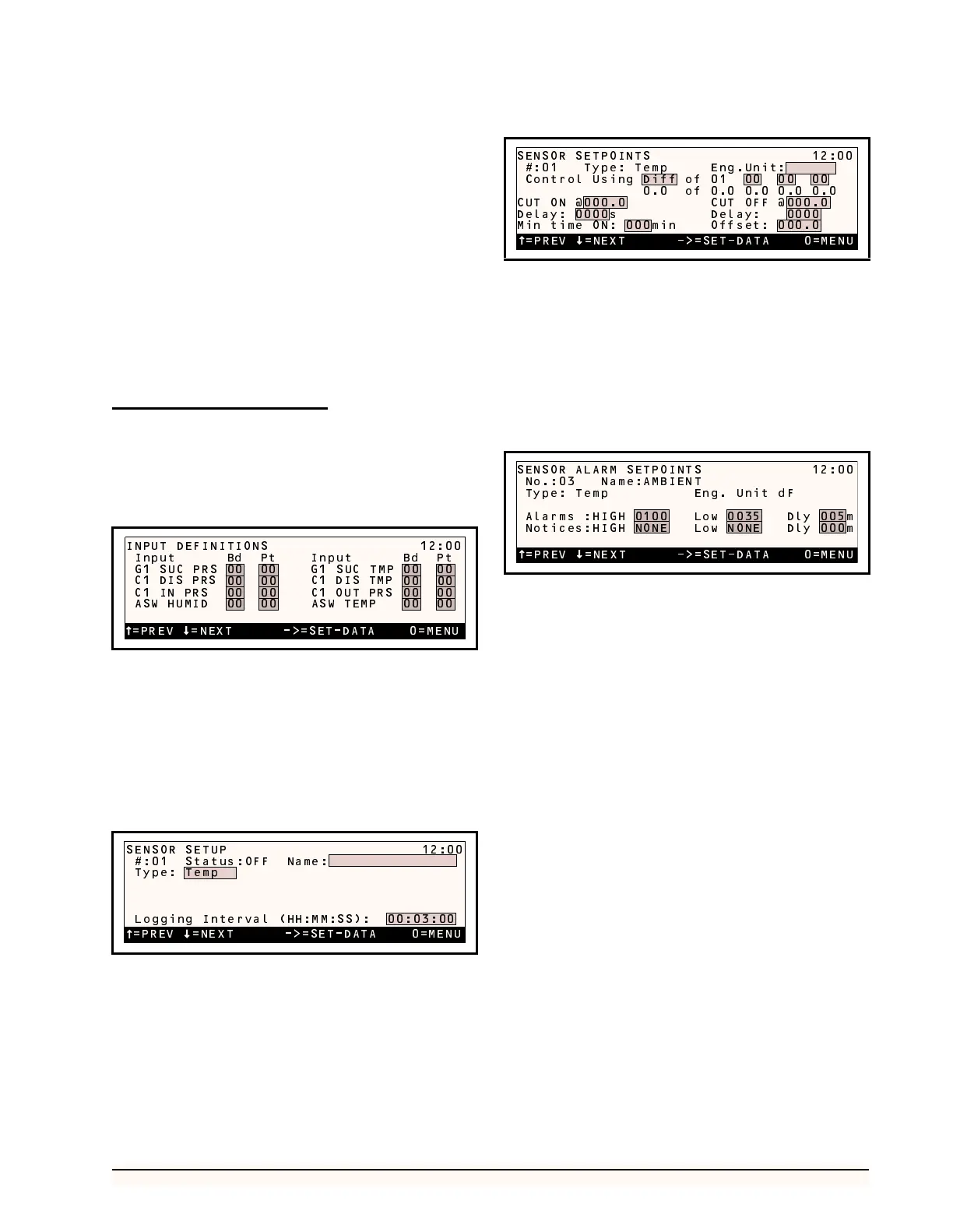
Alarm Setup
If an alarm or notice is required when a particular RT
reading level is reached, the sensor alarm and notice set
points need to be defined in the Sensor Alarm Setpoints
screen (see Section 7.6.2. of the RMCC manual).
Exhaust Fan Setup
In some refrigeration control environments, it may be
necessary to activate an exhaust fan when a refrigerant leak
is detected. To control an exhaust fan with a signal sent by
an RT, a set of ON and OFF set points must be defined, and
the relay output of the fan must be identified within the
RMCC Output Definitions screen.
Cut-On/Cut-Off Setpoints
Cut-on and cut-off set points for sensor-controlled out-
puts are defined in the Sensor Setpoints screen—the same
screen as the RT offsets (see “Offset Adjustment”, above).
In the Cut On field, enter the refrigerant level that,
when exceeded, will turn on the fan. In the Cut Off field,
enter the refrigerant level that will deactivate the fan once
it has been activated. For both set points, a delay may be
specified.
=PREV =NEXT ->=SET-DATA 0=MENU
INPUT DEFINITIONS 12:00
Input Bd Pt Input Bd Pt
G1 SUC PRS 00 00 G1 SUC TMP 00 00
00 00 00 00
00 00 00 00
00 00 00 00
C1 DIS TMP
C1 OUT PRS
ASW TEMP
C1 DIS PRS
C1 IN PRS
ASW HUMID
=PREV =NEXT ->=SET-DATA 0=MENU
SENSOR SETUP 12:00
#:01 Status:OFF Name:
Type: Temp
Logging Interval (HH:MM:SS): 00:03:00
=PREV =NEXT ->=SET-DATA 0=MENU
SENSOR SETPOINTS 12:00
#:01 Type: Temp Eng.Unit:
Control Using Diff of 01 00 00 00
0.0 of 0.0 0.0 0.0 0.0
CUT ON @000.0 CUT OFF @000.0
Delay: 0000s Delay: 0000
Min time ON: 000min Offset: 000.0
=PREV =NEXT ->=SET-DATA 0=MENU
SENSOR ALARM SETPOINTS 12:00
No.:03 Name:AMBIENT
Type: Temp Eng. Unit dF
Alarms :HIGH 0100 Low 0035 Dly 005m
Notices:HIGH NONE Low NONE Dly 000m