30 • Refrigerant Transducer (P/N 809-1550) 026-1701 Rev 0 01-05-98
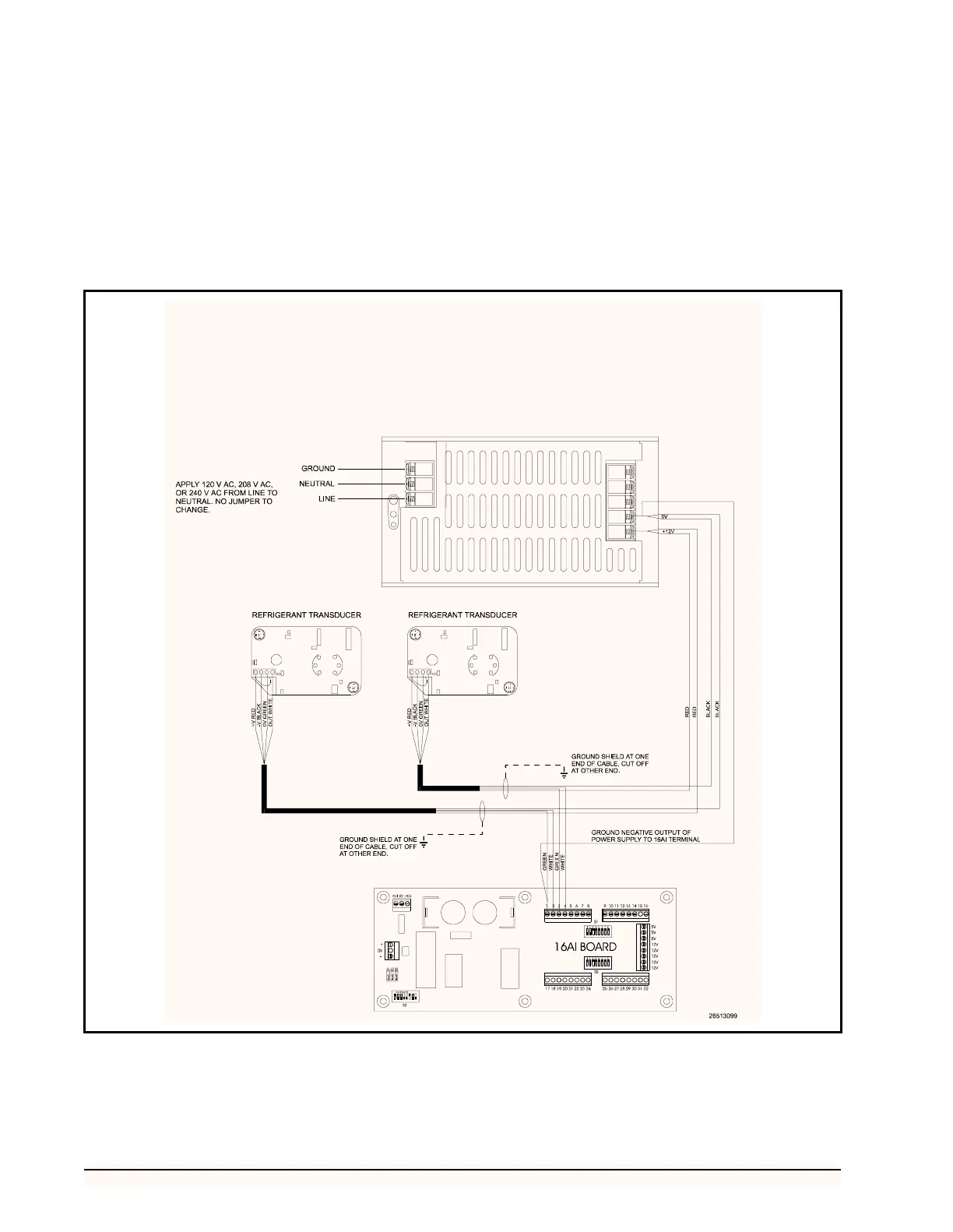
3. Attach the white wire to the OUT terminal of
each of the RTs and an even terminal on the
16AI board input connections.
4. Attach the red wire to the +V terminal of each
of the RTs and the 12V terminal of the power
supply.
5. Cut off the shield at the transducer and
ground at either a ground lug or an odd termi-
nal of the power supply.
6. Ground the negative output of the power sup-
ply to one of the odd terminals of the 16AI in-
put connections.
7. Set the corresponding input switches to the
down position.
Figure 25 - Multiple Refrigerant Transducer Layout