Peripherals Manual Refrigerant Transducer (P/N 809-1550) • 27
Refrigerant Transducer (P/N 809-1550)
Overview
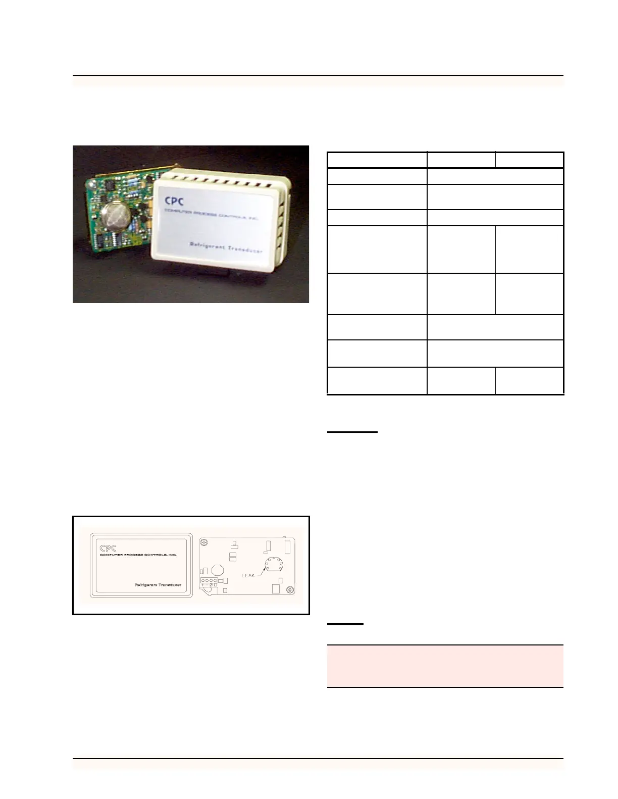
The Refrigerant Transducer (RT) (P/N 809-1550),
shown in Figure 23, monitors a specified area for the pres-
ence of refrigerant. When refrigerant is detected, the RT
sends a signal to a 16AI input board, and to a CPC control-
ler such as the Building Environmental Control (BEC) or
Refrigeration Monitor and Case Control (RMCC). The
16AI input board is capable of supporting up to sixteen
RTs, although an additional power supply is required if
more than one RT is connected to a 16AI board. The clear-
ing cycle, warm-up cycle, and temperature compensation
are unique CPC RT features that reduce false leak signals
and improve leak detection capabilities. The transducer is
enclosed in a protective case to prevent damage to the re-
frigerant sensor.
Refrigerant Transducer Sensor Type
The refrigerant transducer is supplied with either of two
sensors depending on the refrigerant to be detected. Table
6 shows the refrigerant type and the sensor part number that
should be used.
Features
• Can be used with long cable runs
• Compact design
• Low power consumption
• Clearing Cycle eliminates effects of prior refrig-
erant exposure
• Warm-up Cycle prevents false signals during ini-
tial power-up
• Temperature Compensation reduces false signals
during large temperature change conditions
• No calibration adjustments required
Installation
Power
If only one RT is to be used per 16AI board, then the RT
may be powered directly by the 16AI power output connec-
Figure 23 - Refrigerant Transducer (Sensor Removed)
Product Number 209-0830 209-0832
Heater Voltage
5.0 V ± 0.2 V (AC or DC)
Circuit Voltage
Max. 24 V (AC or DC, PS ≤ 15
mW)
Load Resistance
Variable (PS ≤ 15 mW)
Sensor
Resistance
1 kΩ ~ 5 kΩ for
R-22 at 1000
ppm/Air
4 kΩ ~ 40 kΩ
for R-134a at
100 ppm/Air
Change Ratio of
Sensor
Resistance
0.30 ± 0.10
(Rs/Ro)
0.50 ~ 0.65
(Rs/Ro)
Heater Resistance
30.0 Ω ± 3.0 Ω at Room Tempera-
ture
Heater Power
Consumption
VH=5.0 V (835 ± 90 mW)
High Sensitivity
To
R-113, R-22,
R-12, R-11
R134a, R-22,
R-12
Table 6 - Refrigerant Transducer Sensor Part Numbers
RTs require special power considerations during pow-
er-up. Do not substitute other power supplies for CPC
Power Supply (P/N 258-1000).